Interesting thread guys.
I've been working on my Carver TFM-55 power amp that had a 350mV dc offset on the left channel. (right was 3.5mV which is great for a 15 year old amp)
The main culprit was a small diode 1N4148 malfunctioning. This was passing positive charge up through the negative part of the bias circuit.
Once that was replaced I still had 60 mV which I wasn't happy with.
I started looking carefully, I changed a lot of resistors as some had drifted. Trying to use 1% metals in sensitive areas.
Managed to get it down to 32mV.
I suspected one of the transistors 2SC3467 (npn). I changed it to the other channel and bam the dc offset swapped channels.
Strange thing is that the bias sets nicely on both channels but somehow this transistor was causing a little of the dc offset.
I have ordered this transistor (I'm in Uruguay so I have to buy it from UK), so I expect I will get 3-4 mV on both channels when this is replaced.
Also replacing all resistors on RCA board for 1% metal film resistors and putting in some nice new coupling caps. (some idiot had put in 0.47uF 50V electrolytics in the signal path!!)
IMO it is worth it. The overhaul has really brought my old amp back to life. It sounds so sweet now.
Cheers
To get the offset really low you need to match the transistors in the input LTP. Any imbalance causes the actual distortion level to rise slightly although I doubt it's audible. Even just touching one with a finger will warm it enough to cause a noticeable imbalance.
0.47 mfd in the signal path. Depends on what the surrounding impedances are really. It's not neccesarily a problem")
0.47 mfd in the signal path. Depends on what the surrounding impedances are really. It's not neccesarily a problem
To get the offset really low you need to match the transistors in the input LTP.
When you refer to the input LTP are you referring to the RCA input board with the differential transistors?
I've also got some new dif. transistors ordered for the input board.
In my case they are 2SC2240's and 2SA970.
2 of each.
I will see if I can get them to match closely.
better still, try to find a dual transistor for the LTP. they are essentially two transistors, with matched hfe, on the same chip. this will help dc offset due to the matching hfe and thermal tracking. some say these are hard to find sometimes so availability may be an issue but if you can find a good quality one, that is your best bet.
and of course make sure the resistors (if used) in the LTP are matched as close as possible.
and yes, the LTP (long tail pair) is the input differential amplifier Mooly was referring to.
and of course make sure the resistors (if used) in the LTP are matched as close as possible.
and yes, the LTP (long tail pair) is the input differential amplifier Mooly was referring to.
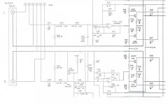
and a part of the main board with the left channel input and feedback loop. Now the collector of Q203 was reading positive when I took out the feedback loop of pin 4.
This should have been negative as it's a push/pull design.
But when the feedback loop was attached again it worked including the bias but I was still getting a little dc offset.
I swapped Q203 for Q204 on the right channel (which was working great), and the dc offset went straight to the right channel. Something was up with the collector on this transistor 2SC3467.
So I need a new one here.
Attachments
back in the 70's +/- 100mV was generally considered good for offset. with servos and other techniques the limits can be improved to less than 50mV on average, with many amps tightly controlled to +/-10mV in production. thump in a speaker gets noticeable at between 100 and 200mV. 100mV across an 8 ohm load would be 1.25 milliwatt, not much. 1 volt would be 1/8 watt, still not much but definitely noticeable thump.
See you figured out how to attach images OK. I tried for ages at the beginning.
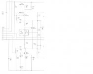
It's really hard to make out from the images, to faint, your just going to have to see what happens.
It's not what I was expecting to be honest, didn't think an opamp would be used as the input stage.
The opamp should see the offset down to practically zero, but without seeing a full circuit Non of the transistors on those images are a LTP, the opamp appears take the place of that.
Would have to see the full circuit -- sorry
It's really hard to make out from the images, to faint, your just going to have to see what happens.
It's not what I was expecting to be honest, didn't think an opamp would be used as the input stage.
The opamp should see the offset down to practically zero, but without seeing a full circuit
Non of the transistors on those images are a LTP, the opamp appears take the place of that.Would have to see the full circuit -- sorry
Hi Unclejed,
I asked this once,
http://www.diyaudio.com/forums/showthread.php?s=&threadid=116731&highlight=
Still wonder.
I asked this once,
http://www.diyaudio.com/forums/showthread.php?s=&threadid=116731&highlight=
Still wonder.
It's not what I was expecting to be honest, didn't think an opamp would be used as the input stage.
Well I'm still learning about this amp.
The design is rare. It has a magnetic field supply with a triac.
Apparently very few technicians know how to work on these carver amps.
Bob Carver became very well know in the 70's for the design. He managed to design an amp that would produce a huge amount of power producing very little heat in a very light package.
http://en.wikipedia.org/wiki/Bob_Carver
There is only 1 guy recommended in the whole of USA.
Think you will find the amp stages pretty conventional. Carvers designs seem more about, dare I say quantity.
Yes true, there is not shortage of power. Loads of headroom. But I love the sound of this amp. It has something special, not just quantity.
Have you listened to any of the TFM series?
Also I know Carver owners who's amps have been destroyed by technicians thinking they were conventional.
There are two clever ideas that seperate a Carver magnetic field amp from a 'normal' amp.
In a regular amplifier power supply, the incoming AC (120 volts at 60 cycles in the US) runs through the primary of a transformer. Tightly coupled with the windings of the primary are the secondary windings, which 'pick up' a portion of the AC; it's 'induced; onto the secondary windings. Very much simplified, but, for examply, a 2:1 turns ratio will give you half the input AC (60V).
That AC is then 'rectified' by a diode bridge into DC, then filtered by large capacitors, which store the charge between cycles and smooth out the ripple voltage.
That DC then powers the amplifier (just skipping alot here to keep it simple).
In a Carver magnetic filed power supply, you have what looks quite similar to a transformer; but they call it a magnetic coil. It has a MUCH higher primary to secondary turns ratio, so much so that it can't tolerate 'full duty cycle' AC; it'll tear itself apart if it's 'on' the entire 60 cycles.
There's a device in series with the primary called a triac, which acts like an on/off switch. The triac turns the coil on in short bursts, and the secondary of the coil is rectified and filtered as before.
As demand for current increases (more volume or more demanding load) the triac control circuit lets the mag coil stay 'on' longer, up to it's safe limit.
The advantage of this is that the mag coil isn't sitting at idle running wide open as in a traditional transformer, so it builds up less heat from energy that's just being wasted.
Hi,
No I've never listened one so it's unfair to comment on the sonics.
The triac behaves a bit like a bi directional transistor that only begins to conduct when a trigger pulse is applied to the gate. The current flows as if it were a forward biased diode and the device remains conducting the current reduces to zero. This reducing to zero happens every cycle at mains rate. Triac control is very efficient and used a lot in power engineering.
Let is know how you get on with the offset issue
- Status
- This old topic is closed. If you want to reopen this topic, contact a moderator using the "Report Post" button.
- Home
- Amplifiers
- Solid State
- Amplifier DC Offset - How Much is OK?