davidallancole said:I would try using an ac voltage source in the similation that has the same peak voltage. Check it against your output signal and you will see if it strays from the signal much.
Good advice!
Zeus, try to make a FFT from the Inputsignal, and compare this with the output!
Why not use 1us...10us timesteps for 20kHz signal....when the whole simulationtime becomes not boring long!
Regards
Heinz!
Drift
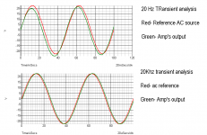
I have reduced the value of R3 to 820R seems to balance the LTP in the CAD, reduced C5 to 22pF. I did a Transient analysis as recommended by powerbecker and attached you can see the drift that occurs. The drift is very minimal at 2Khz(not shown), slightly higher at 20KhZ. But is more noticeable at 20Hz.
I have reduced the value of R3 to 820R seems to balance the LTP in the CAD, reduced C5 to 22pF. I did a Transient analysis as recommended by powerbecker and attached you can see the drift that occurs. The drift is very minimal at 2Khz(not shown), slightly higher at 20KhZ. But is more noticeable at 20Hz.
Attachments
Keith, c4 is part of the zobel, and c6 is a charge suck out cap, reducing crossover distortion at higher freqs. Only c1 and c5 are part of the feedback compensation.
Without the zobel network you risk local oscillation of the output stage (~20mhz, not caused by global feedback) This will never show up in sims and can only be verified with a scope.
Mike
Without the zobel network you risk local oscillation of the output stage (~20mhz, not caused by global feedback) This will never show up in sims and can only be verified with a scope.
Mike
Hi,
It is simply easier/quicker to scope the real circuit.
if your model excludes all the real life Ls & Cs that form the PCB traces and component/leads as well as the real device characteristics.This will never show up in sims
It is simply easier/quicker to scope the real circuit.
Mike
Sorry it was a statement and not a question - probably better understood when spoken.
Your reply did not make sense until I saw the other scheamatic - In which Zues has changed the component values.
It would be a lot easier if reference designators kept unique numbers and did not reuse existing ones when changes are made - perhaps the software is to blame.
My "statement" stands but should read "C6 and C5" for the other diagram.
All reactive components are potential sound changers or stability upsetters even if they do a good job sucking high.
Keith
MikeB said:
Without the zobel network you risk local oscillation of the output stage (~20mhz, not caused by global feedback) This will never show up in sims and can only be verified with a scope.
Mike
Mike, could you tell something more about your experience with output stage oscillation, please. Concerning driving impedance, base resistors and zobel networks?
regards
Adam
Still having problems with stability..?
Try the following:
1. Add a small cap to the input, from base to gnd on Q1 (22-100pF) and a series resistor (min 100 ohms) between R22 and the base of Q1;
2. Discard C5 completely
3. Increase R19,R20 to 33+ ohms
If this does not solve all the stability issues:
4. Add 100-500pF (250V) b-c to Q6, Q7 (test the minimum value).
5. If you have actually built a real model, check your ground topology for overlapping signal paths along a "clothesline" ground trace.
An amp circuit should be stable without the need for a Boucherot network in its output. Adding it is a "dirty fix" to stability problems, not a solution. Adding a series inductor in the output will cause more problems than it would apparently solve, IMHO.
Re simulations: I use a 10ms window size, 1us step size for a 1kHz input signal. The simulations have been consistent with subsequent THD+N measurements, which are usually better on the real model.
Hi Apd regarding what you mentionned:
Try the following:
1. Add a small cap to the input, from base to gnd on Q1 (22-100pF) :-
i tried this with 100pf but gave oscillations i'll try with 33pf should be more stable.
and a series resistor (min 100 ohms) between R22 and the base of Q1; Are you sur its R22 you are talking about?
2. Discard C5 completely:-ok
3. Increase R19,R20 to 33+ ohms Were 68R but i reduced them to 22R to help balance the LTP
If this does not solve all the stability issues:
4. Add 100-500pF (250V) b-c to Q6, Q7 (test the minimum value).
I'll give this a try just in case
5. If you have actually built a real model, check your ground topology for overlapping signal paths along a "clothesline" ground trace. I/p section gnd joined by a single track to speaker gnd and psu gnd
Hi,
Can you explain?
What?Turn off any lossy compression
Can you explain?
Hi,
Smaller Rs here allow variations in transistor characteristics to dominate. Larger values help to paper over device variations. The largest value normally used develops 600mV when quiescent current passes, but useful correction is achieved with as little as 100mV of DC on the degeneration resistors.
In the real PCB never take your speaker return back to the PCB, instead take it to your audio ground (central star ground).
The input ground (signal ground or clean ground) should never share a common track with any dirty grounds.
Use a separate return from the PCB to audio ground for each of the clean and dirty grounds. Some designers then link the clean and dirty grounds on the PCB with a low value resistor (have a look at a selection of schematics, 10r is often used).
this is NOT how to balance the LTP.Were 68R but i reduced them to 22R to help balance the LTP
Smaller Rs here allow variations in transistor characteristics to dominate. Larger values help to paper over device variations. The largest value normally used develops 600mV when quiescent current passes, but useful correction is achieved with as little as 100mV of DC on the degeneration resistors.
in the simulator or the real PCB?I/p section gnd joined by a single track to speaker gnd and psu gnd
In the real PCB never take your speaker return back to the PCB, instead take it to your audio ground (central star ground).
The input ground (signal ground or clean ground) should never share a common track with any dirty grounds.
Use a separate return from the PCB to audio ground for each of the clean and dirty grounds. Some designers then link the clean and dirty grounds on the PCB with a low value resistor (have a look at a selection of schematics, 10r is often used).
Not only do we have reference designators changing but now Zobel cells become Boucherot networks ? Surely a Zobel network with no L should be a Zobe !
Zeus
I think CBS240 had the solution to your stability problem way back in this discussion when every one was chatting about step sizes and adding capacitors and networks (cells).
It is likely that there is interaction between Q9 and Q10 (inside the loop you are trying to correct) and separate biasing for Q9 and Q10 as CBS240 suggests may just cure the problem.
You should apply the change to your first "basic" design (with de-coupling after R23 and R24) - As you state the extra capacitors appear to be making things worse and may mask the benefit of the cure let alone screw up the sound reproduction.
Regards
Keith
darkfenriz said:Mike, could you tell something more about your experience with output stage oscillation, please. Concerning driving impedance, base resistors and zobel networks?
regards
Adam
Hi Adam, i had this experience with at least 2 completely different amps, one was a quasi complementary (MJL21194), the other EF with MJL3281/1302.
The amps looked stable when beeing first powered up, but the moment a speaker cable was connected (3 meters) i had oscillation, ~20mhz, 50mv (varying with temperature of outputdevices). It did not make any difference if speaker was connected or not. Measuring at different stages of the amps showed that the 20mhz signal was strongest at output, much weaker already at emitters of drivers and nearly not visible in vas. This (and the high frequency) excluded instability caused by feedback loop. The first i tried was adding base stoppers, these greatly reduced the effect, but did not stop it. Adding the RC at output stopped it at once.
Since this time i never built an amp again without zobel and never again had that problem.
I had a conversation with Graham Maynard about this, he confirmed that problem, it seems to be caused by the steep rising ft of modern fast transistors.
Another experience about base stoppers was with my symasym, shorting the 22ohm base stoppers to the drivers made them oscillate with 36mhz.
An amp having any stability issue somewhere, no matter how small, will sound completely bad. (unprecise and lifeless, muffled if permanently oscillating, harsh and bright if temporaly oscillating)
These problems can only be detected by careful scoping...
I believe that the output coil is optional (if stability margin is BIG), the RC at output not. Skipping it will bite you, the amp might suddenly oscillate without any obvious reason. A RC at output is in my opinion in no way a "dirty fix", it's a must, especially for ClassAB with modern transistors.
About the step size in sims, i typically simulate with 20khz, using a window of 0.1 to 0.3ms, stepsize of 10ns. The stepsize needs to be that low to enable sims showing stability issues. With a stepsize of 1us, it can not show frequencies above 500khz, but oscillations are typically at several Mhz. This way stability problems (even without visible oscillation) show up in the fft as a "mountain" around the resonance frequency.
Mike
zeus_threat said:Hi Apd regarding what you mentionned:
Try the following:
1. Add a small cap to the input, from base to gnd on Q1 (22-100pF) :-
i tried this with 100pf but gave oscillations i'll try with 33pf should be more stable.
and a series resistor (min 100 ohms) between R22 and the base of Q1; Are you sur its R22 you are talking about?
Sorry, not R22, but R10 - the input biasing resistor. Why do you put the value above the part anotation? Quite confusing..
")
The idea is to have a HF return path to ground for the input base, otherwise all kinds of phenomena may occur due to stray capacitances and the differential amp will not work correctly for HF.
The resistor in series with the first base would form a HF-Low Pass filter together with the new cap to ground. If you insert it before the R10 connection point, a small attenuation will occur. After R10 - some bias voltage imbalance and output offset, which can be compensated with an equal value resistor in series with the other base of the diff.amp.
The input cap is usually even higher than 100p. Increasing it should NOT lead to stability problems. C5 is probably to blame, assuming a *correct* pcb topology.
Fast decoupling caps to ground are mandatory after R23, R24. 0.1uF minimum value. I would add one on each side of these resistors.
Run an AC Sweep up to 20MHZ, dividing the output voltage by the voltage difference between the bases of the input transistors. This would give you information on the 'open loop gain' of the circuit. Watch for a rise in the gain at high frequencies, coupled with phase rotation - quite often the problem. It's a good idea to set the pole of the input HF filter below the frequency of any peak in the open-loop gain.
Hi Apd,
you prefer
I prefer to take RCA ground via screened cable to PCB input ground and from PCB input ground to audio ground. Both these ground connections on the PCB are very close to the input connection.
This seems to work. Why would your layout be better or under which operating circumstances does it offer an advantage?
you prefer
a ground connection from the input jack to p/s ground
I prefer to take RCA ground via screened cable to PCB input ground and from PCB input ground to audio ground. Both these ground connections on the PCB are very close to the input connection.
This seems to work. Why would your layout be better or under which operating circumstances does it offer an advantage?
- Status
- This old topic is closed. If you want to reopen this topic, contact a moderator using the "Report Post" button.
- Home
- Amplifiers
- Solid State
- Amp distortion