Evertything finished except front and back
Hi,
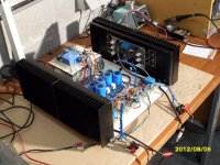
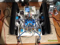
Amp is running perfect
-bias is lightly decreasing when temperature is goiing. (drops very little: from 180mA/15°C to 175mA/40°C)
-Protectionboard with the TA7317 is doiing his job properly.
-DC-servo is keeping output offset well below 2mv.
-Static DC control is funcioning perfect: this makes sure that DC-offset is already very low (+-10mv) when the output relay kicks in.
Must admit that I maybe hat to put small heatsinks on the HFA25PB60 rectifier diodes.
The topside will be made out of 6mm glass.
Front and back panel is something else, I'm looking for nice wood, which I want to varnish with a lot of layers to make it very, very smoot.
Hi,
Amp is running perfect
-bias is lightly decreasing when temperature is goiing. (drops very little: from 180mA/15°C to 175mA/40°C)
-Protectionboard with the TA7317 is doiing his job properly.
-DC-servo is keeping output offset well below 2mv.
-Static DC control is funcioning perfect: this makes sure that DC-offset is already very low (+-10mv) when the output relay kicks in.
Must admit that I maybe hat to put small heatsinks on the HFA25PB60 rectifier diodes.
The topside will be made out of 6mm glass.
Front and back panel is something else, I'm looking for nice wood, which I want to varnish with a lot of layers to make it very, very smoot.
Attachments
Upgrade or downgrade soundwise??
Hi,
I've clearly made a mistake by using resistive loading on the VAS to increase openloop bandwith. Some members pointed me this out. Douglas Self and Bob Cordell are telling the same in their literature.
Instead of resistive loading I would like to use local feedback arround the VAS stage.
Please have a look at the PDF document and tell me this is the right way to go??
Thanks in advance
Attachments
Upgrade results + oscillation
Hi,
The change from above is an upgrade! The sound hase more detail! The hights sounds much better.
From the start on I heard some buzzing throught the speakers. First I thought it had to do with the messy wiring in the begin. But even now I hearing buzzing throught the speakers.
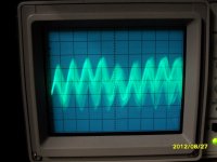
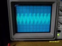
I did a bit invesigation with the scope:
==> I'm having +-10Mhz oscillation with 50mV amplitude! It looks as if the 10Mhz is running on top of a triangle like signal with a frequency of +-2Mhz.
What have I tried:
1) grounding the heatsinks => NOK
2) played with the zobel capacitor ==> 10R +10N/100N/1µ ==> NOK
3) played with the OPS BIAS ==> Nothing changes
4) disconnected 1 amplifer in total (no ground loops) ==> Nothing changes
Can someone give me a tip?
See the pictures below.
Hi,
The change from above is an upgrade! The sound hase more detail! The hights sounds much better.
From the start on I heard some buzzing throught the speakers. First I thought it had to do with the messy wiring in the begin. But even now I hearing buzzing throught the speakers.
I did a bit invesigation with the scope:
==> I'm having +-10Mhz oscillation with 50mV amplitude! It looks as if the 10Mhz is running on top of a triangle like signal with a frequency of +-2Mhz.
What have I tried:
1) grounding the heatsinks => NOK
2) played with the zobel capacitor ==> 10R +10N/100N/1µ ==> NOK
3) played with the OPS BIAS ==> Nothing changes
4) disconnected 1 amplifer in total (no ground loops) ==> Nothing changes
Can someone give me a tip?
See the pictures below.
Attachments
c3, 4, 6, 7, 8 & 9 are all compensation as are r8 & 9.
Try increasing Miller comp around the VAS. That is the simplest and the results may give a clue to where you aim next.
Why did you choose 10n for the output Zobel?
How is it terminated? Does it have a long loop back into the output stage? If the loop is too long the inductance may be creating an impedance that prevents the Zobel doing it's HF job.
Thanks Andrew,
I will play arround a bit with the Miller comp the next days.
Concerning the zobel network. Both speaker output, zobel connection and feedback to IPS is only max 10mm from each other on the PCB. The 10n zobel cap is choosen without stability testing what so ever, I use 10n because it is a common value used for the zobel.
In general I've learned more things from this amp than I expected, and that's good.
Luckily I swapped my matched output pairs with a testing pair. Because with testing other freq comp caps I managed to kill a pair of 2SK1530/2SJ201.
I increased the Miller comp from 33pf to 68pf, at the output of the drivers I measured +- the same oscillation. Also with connecting a speaker at the output of the drivers I heard exactly the same as with the 33pf miller comp.
I increasedthe gate stoppers from the drivers 2sk2013/2sj313 from 100R to 470R ==> no change.
I have no idea what is causing the hum/oscillation.
I think I'm gonna swap the driver FET to BJT's, jus to see what will happen.
Amp is still humming
After some trial and error testing, I still haven't found what is is causing the humming through the speakers.
The hum is a sinus signal with a frequency of +-160Hz, measured on a scope.
Whe I keep my ear close to the transformer (amplimo 625VA), the transformer is making the same noise/hum as the speakers?
Any suggestion
Attachments
![HPIM2007%20[800x600].JPG](/community/data/attachments/280/280738-1ca4f69004bf2db22f49a880dec00bc7.jpg)
new design
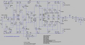
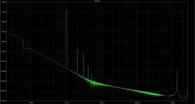
During solving all issues discussed above and searching for solutions, I designed in parallel a new amp.
- better VAS ==> more dominant 2nd ant 3th harmonic during FFT analysis
- MKP input capacitor instead of MKT
- 33R - 470µF buffer between rails and LTP/VAS section
- BJT drivers instead of FET's ==> big improvement in sound! ==> much more depth in music
- better input bjt's (1775/872 instead of 3381/1349)
See the attachment of the current design states. I put in a jumper to select High Open Loop Bandwith.
Attachments
I've asked one of the operators to change the thread title, sofar I haven't received an answer.
Changed it. Better use the report post triangle symbol, the one with the exclamation mark inside it for such requests also, so it goes in the reports queue that every mod sees, avoid PMs, they don't expect forum related requests there for sure.

Upgrade + listening impression
A lot happened the last weeks.
- first I've said that changing the drivers from FET to BJT's improved the sound (more depth in the music)
- but after more listening, I liked the FET's as drivers more ==> a lot more detail/contrast in the music
==> disconnecting the middle point of the driver outputs with the ouput of the amp changed a lot.
I still have the PMA700V amp to compare with. At this point I for sure like my amp more than the PMA700V, my amp has more details in the hight's and better base response.
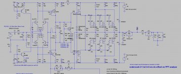
Have a look at the attachement, this is where I'm working towards. At this point the VAS degeneration is stil 560Ohm and LTP source resistors are 2K2. All the rest is identical.
A lot happened the last weeks.
- first I've said that changing the drivers from FET to BJT's improved the sound (more depth in the music)
- but after more listening, I liked the FET's as drivers more ==> a lot more detail/contrast in the music
==> disconnecting the middle point of the driver outputs with the ouput of the amp changed a lot.
I still have the PMA700V amp to compare with. At this point I for sure like my amp more than the PMA700V, my amp has more details in the hight's and better base response.
Have a look at the attachement, this is where I'm working towards. At this point the VAS degeneration is stil 560Ohm and LTP source resistors are 2K2. All the rest is identical.
Attachments
Stability tests on final version
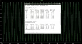
I made a proto PCB from the final circuit below, in order to make some decent stabiltity tests.
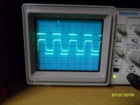
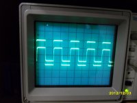
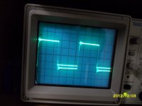
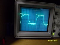
personaly, I think this version sounds terrific. But besides sounding good, it has to be stable. I don't have much experience yet in square wave testing. Therefore I've attached pictures of the scope readings. The filename of the picture is: peak-peak voltage / Freq / 8R / C-load. The last two pictures are done wihth 4Vpp instead of10. If I increased the ouput voltage higher then 4Vpp with this load, there was massive ringing on the square wave.
Can anyone tell me whether i'ts good enough for home use?
Greetz
I made a proto PCB from the final circuit below, in order to make some decent stabiltity tests.
personaly, I think this version sounds terrific. But besides sounding good, it has to be stable. I don't have much experience yet in square wave testing. Therefore I've attached pictures of the scope readings. The filename of the picture is: peak-peak voltage / Freq / 8R / C-load. The last two pictures are done wihth 4Vpp instead of10. If I increased the ouput voltage higher then 4Vpp with this load, there was massive ringing on the square wave.
Can anyone tell me whether i'ts good enough for home use?
Greetz
Attachments
- Status
- This old topic is closed. If you want to reopen this topic, contact a moderator using the "Report Post" button.
- Home
- Amplifiers
- Solid State
- Amp design for subwoofer and wideband duty