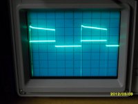
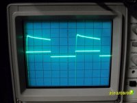
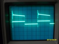
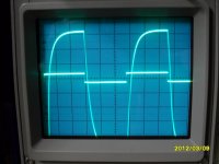
The 10kHz square wave has a strange rising form?
Could it be the combination of the output impedance of the function generator (Zout = 50Ohms) and the 10µ capacitor of the HP filter from the amplifier?
It is wise to bypass the HP filter when using a square wave signal as input signal?
Thanks
Could it be the combination of the output impedance of the function generator (Zout = 50Ohms) and the 10µ capacitor of the HP filter from the amplifier?
It is wise to bypass the HP filter when using a square wave signal as input signal?
Thanks
Attachments
The 10kHz square wave has a strange rising form?
Could it be the combination of the output impedance of the function generator (Zout = 50Ohms) and the 10µ capacitor of the HP filter from the amplifier?
It is wise to bypass the HP filter when using a square wave signal as input signal?
Thanks
Hi
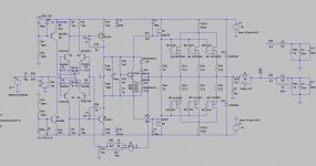
This is b/c of your C2 (schematics in post #63) that is way too high. It should be more in the range of 1nf (or less) but not 10nf (even if you have 430 ohm at input). Also, a 10nf like that will fom a low pass filter with your source output impedance that will add up to the 430 ohms...
Personnally I would increase 430 ohms to about 1500 ohms and then use C2 at about 330pf as a start. Some will say that the feedback path is no more "balanced" with your input path (430 ohms for R43 and R41) but for an audio amp that is not important (if we exclude the 12k resistors that should be similar value for DC offset...)
Fab
Last edited:
 thus you do not need to change anything
 High DC-offset when no servo is used
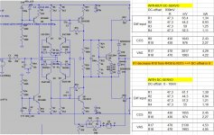
During simulations: Spice error log shows a DC-offset of -552mV
In practice: I measured -660mV
Differential input is made by 2SC3381/2SA1349 monolithic bjt's.
Input serieristor has same value as feedback resistor.
The offset looks much to high, but I can't understand wy, I've tried with simulation to find out what causes this offset. With removed OPS and taking feedback from drivers doesn't change the offset.
As DC-servo or lowering the CCS resistor for the positive LTP is an option I know, but I wan't to understand the origin of the offset.
Thanks.
Attachments
I think when you measure the voltage drops across each of R1 R2 R3 & R4 you will find that the LTP quiescent currents don't match.
Did you select those resistors to 0.1% matching?
The inequality of the LTP currents is down to selecting the wrong values for the Collector Vdrops, (wrong resistor values), or biasing the VAS to other than 4mA.
Did you select those resistors to 0.1% matching?
The inequality of the LTP currents is down to selecting the wrong values for the Collector Vdrops, (wrong resistor values), or biasing the VAS to other than 4mA.
Thanks for the tip, I'll focus on these values tommorow and match those resistors.
The VAS current measured:
- at positive rail side: 4.4mA
- at negative rail side: 3.8mA
This is a big difference indeed, I'm curious what it will be after matching of collector resistors of LTP.
But, still, I wonder wy also the simulation gives -552mV dc offset. In the sim world are all values and parameters perfect?
Hi,it's the LTP current that should be matched, so that the LTP is balanced. Measure the balance across the emitter resistors.
This requires you to change the voltage across the collector resistors and/or change the current through the collector resistors.
Give views sevens with a JFET BS170S with input having resistance 1MOhm, gain up to 10x and the output resistance to max 1kOhm.

Thanks and Cheers!

Hi Andrew,
I've swapped the resistors. I matched the 47Ohm resistors with my multimeter => to 1/10 Ohm reading.
I've measured and collected all currents from LTP/CCS and VAS, this with and without DC-servo.
When running without the servo I did one other test ==> I had to lower the CCS resistance for the positive LTP from R430 to R315 to have an offset of 0.
Greetz
Attachments
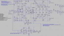
I understand it, the only option to avoid big DC-offset's at startup is to adjust the bias of the LTP.
But, I don't like trimmers on the amp pcb. So I turned another way with this.
I regulate the CCS for the LTP, with;
- A 10K trimmer (P21/22) with a voltage devider (R100/101/102)
With this I can set the startup DC-offset to 0V, this avoid a startup thump
due to 600mV offset when the relay kicks in.
- A DC-servo for the dynamic DC-offset ==> Phase shift of this DC-servo is 0°
and has 75dB at 10Hz.
At the moment is running in real life.
Attachments
when setting up the amplifier you need to trim the voltages so that Ir1= Ir2 and that Ir3=Ir4
That gets the two LTPs into balance.
Then set DC output offset to zero by adjusting input Rin or adjusting VAS or setting the DC servo to work if offset is already low when the amp is cold.
That gets the two LTPs into balance.
Then set DC output offset to zero by adjusting input Rin or adjusting VAS or setting the DC servo to work if offset is already low when the amp is cold.
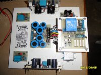
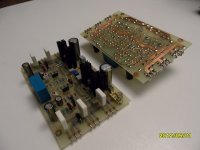
Update
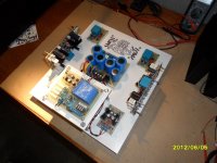
All pcb's are ready except the protection board based on the TA7317 chip.
The heatsinks have to be ordered: 4 pieces 200mmx165mm from modushop.
Pcb's are all made with the toner transfer method, cleaned and varnished afterwards.
Enjoy the pictures.
All pcb's are ready except the protection board based on the TA7317 chip.
The heatsinks have to be ordered: 4 pieces 200mmx165mm from modushop.
Pcb's are all made with the toner transfer method, cleaned and varnished afterwards.
Enjoy the pictures.
Attachments
Compared with DENON PMA700V
I had the opportunity to do a listening test of my amplifier compared to a DENON PMA700V.
I must admit, the DENON sounded warmer and had more depht in the music.
I wonder what the mean reason is for this?
Could it be the open loop bandwith? This is according to simulation +-7Khz.
Still, I will finish the amp completely and doiing some research for the next.
Greetz
If I could edit the thread title, I would have done it.
Yes, the idea is to use it for a subwoofer, and indeed the complexity is a bit overkill for a sub amp.
But, this was for me a learning project for a next amp.
Concerning power, there are two amp PCB's which are delevering more than 250Wrms/8r for my peerless xls12 sub,this is more than enough for me.
Greetz
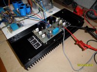
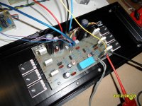
Update: one channel finished
Andrew, I've asked one of the operators to change the thread title, sofar I haven't received an answer.
Regarding the comparisation with the Denon PMA700, I noticed when I increase Bass and treble on my equalizer, my amp sound much more like the Denon.
The heatsinks have arrived. I use 4 heatsinks of 165x200mm from Modushop.
With a welded metal construction I connect two heatsinks to eachother and can mount them on the bottom plate.
Attachments
- Status
- This old topic is closed. If you want to reopen this topic, contact a moderator using the "Report Post" button.
- Home
- Amplifiers
- Solid State
- Amp design for subwoofer and wideband duty