for parallel , that's no brainer :
-parallel inputs (GNDs already shorted , short hots , either with Y RCA cable , or U link pushed in 2 & 3 XLR )
-parallel outputs (GNDs already shorted , remember - these are red ones , also you need to short together hots (black ones) ..... use short wire for that)
- output is same as with regular connection - one speaker wire on Red post , second speaker wire on Black post
Got it, Zen!!
Many thanks!
I am building one of the kits from the diyaudiostore.com
I noticed something about the brown backing material the keratherm is supplied on. I have seen this stuff before.
I once bought this with sticky backing to replace mouse feet that have gone missing.
So don't throw that brown backing material away, stick it on your mice!
I noticed something about the brown backing material the keratherm is supplied on. I have seen this stuff before.
I once bought this with sticky backing to replace mouse feet that have gone missing.
So don't throw that brown backing material away, stick it on your mice!
The Amp Camp Amp V1.6 Build Guide is now online. Thank you very much 6L6 for another magnificent build guide.
The Amp Camp Amp V1.6 Build Guide is now online. Thank you very much 6L6 for another magnificent build guide.
What Jason said.
Nice piece of work 6L6. Looks like you've done well with your coverage of the various build options. From a first pass, read clearly to me. I'm sure doing by kit builders will generate some useful comments at various steps.
Pass DIY Addict
Joined 2000
Paid Member
Super awesome build guide, Jim! I found nothing wrong with the previous ones, but it looks like this one is a nice step forward in formality and clarity. Nicely done. I appreciate the huge number of hours to make all of those images (not to mention the nice photographic technique) and clearly document each step. Thank you!
https://d17kynu4zpq5hy.cloudfront.net/igi/diyaudio/aBfLVPPWfjxQ1dR2.huge
Uhm, I have two sets of 22 awg wire (one pair red/white solid, one pair green/blue stranded). Is the 18 awg wire pair (red/black, approx 50 cm each) long enough to make all connections?
In the pictures it often looks like the solid wire pair is used for V+ and GND.
Uhm, I have two sets of 22 awg wire (one pair red/white solid, one pair green/blue stranded). Is the 18 awg wire pair (red/black, approx 50 cm each) long enough to make all connections?
In the pictures it often looks like the solid wire pair is used for V+ and GND.
Last edited:
Alan4411 said:I have a silly suggestion, swap the 2 boards over, does the fault follow the board or the location?
Alan
I did the swap and it was location. The white RCA is shorted. Solder flowed underneath the center pin and it got connected to the outer edge(negative?) of the socket. Replaced it and the amp has sound now from both sides.
Listening to both amps now connected from the xlr outputs of my preamp and no loud sound from speakers when turned off.
One other thing though, resistor #15 reads .699 plus or minus, instead of 2.2k on all the PCBs in both the amps. I was working fast building these amps I might have missed the values. All other resistors tested ok.
Thanks all again for the help and suggestions. Amps sounding great.
Last edited by a moderator:
cRomer,
Glad you have it sorted, enjoy it now.
Re: R15. You cannot directly resistance test it in circuit. It is effectively paralleled by R8 (so a 680/700 figure is in the right range) and is across the emitter / base junction of Q3.
Your best check is the colour code red, red, black, brown, brown. (It is the only resistor in the kit starting with red, red so a give away really.)
Last edited:
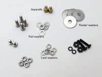
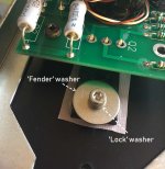
Little lost on step 14. Point 3 reads
"There should be a lock washer (split washer, spring washer) between the fender washer and the screws."
Is this saying the image is wrong? What's the lock washer? Does it go transistor-lock washer-fender washer-top of screw. Or transistor-fender-lock washer-top of screw?
Thanks
"There should be a lock washer (split washer, spring washer) between the fender washer and the screws."
Is this saying the image is wrong? What's the lock washer? Does it go transistor-lock washer-fender washer-top of screw. Or transistor-fender-lock washer-top of screw?
Thanks
The idea is to provide the most uniform pressure on top of the transistor against the heatsink.
The best way to achieve this is to put the larger flat washer over the transistor: this will apply the uniform pressure in the largest available area.
On top of that you want a pressure washer that will offset any misalignment between the screw head and the large flat washer. It will also prevent vibrations and other variables to loosen the screw.
On top of that you want the screw head making the pressure against the lock washer.
Does this make sense? I find it easier to understand things when they have a reason behind them instead of just recipes to follow.
Hope this helps,
Best regards,
Rafa.
Little lost on step 14. Point 3 reads
"There should be a lock washer (split washer, spring washer) between the fender washer and the screws."
Is this saying the image is wrong? What's the lock washer? Does it go transistor-lock washer-fender washer-top of screw. Or transistor-fender-lock washer-top of screw?
Thanks
Yes, the lock washer is not shown. See pictures. It goes pad, transistor, 'fender' washer, 'lock' washers then screw (bolt).
Reasons as Rafa says.
Attachments
Last edited:
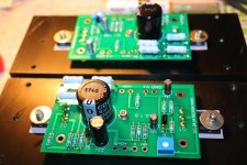
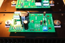
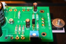
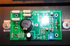
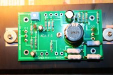
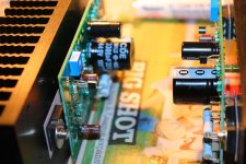
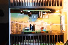
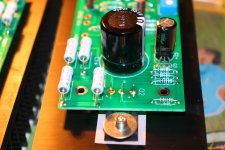
Soldering the ACA 1.6 amps
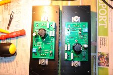
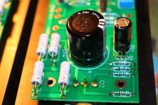
Hey all, I built my ACA 1.6 PCB's and put them on the heath-sinks. I plan to build another ACA for dual mono configuration, but I will first build this one in stereo and test it in my sound system. It was fairly easy to put all components together thanks to 6L6's excellent build guide. As I always do, I used no clean flux paste on all the solder pads and -joints, which lets the hot solder flow evenly over the pads and you get beautiful solder joints. I used a Weller temperature regulated soldering station with differently sized screwdriver tips; temperature was 300 degrees centigrade on the bigger parts / pads, and 250 degrees centigrade on the more vulnerable parts like the small transistors. I also used a small crocodile clamp with a small piece of folded aluminium foil clamped on the transistor legs on the other side of the PCB whilst soldering them, to keep them cool. This is especially important with "unobtanium" parts. The lead-free solder with rosin-core I used contains 96.5% tin, 3% silver and 0.5% copper, with a melting temp of 200 C.
I hope to finish both amps in the coming weeks and test them in stereo and in bridged mono.
Hey all, I built my ACA 1.6 PCB's and put them on the heath-sinks. I plan to build another ACA for dual mono configuration, but I will first build this one in stereo and test it in my sound system. It was fairly easy to put all components together thanks to 6L6's excellent build guide. As I always do, I used no clean flux paste on all the solder pads and -joints, which lets the hot solder flow evenly over the pads and you get beautiful solder joints. I used a Weller temperature regulated soldering station with differently sized screwdriver tips; temperature was 300 degrees centigrade on the bigger parts / pads, and 250 degrees centigrade on the more vulnerable parts like the small transistors. I also used a small crocodile clamp with a small piece of folded aluminium foil clamped on the transistor legs on the other side of the PCB whilst soldering them, to keep them cool. This is especially important with "unobtanium"
parts. The lead-free solder with rosin-core I used contains 96.5% tin, 3% silver and 0.5% copper, with a melting temp of 200 C.I hope to finish both amps in the coming weeks and test them in stereo and in bridged mono.
Attachments
-
 IMG_2447.jpg917.7 KB · Views: 518
 -
 IMG_2448.jpg692.8 KB · Views: 510
 -
 IMG_2450.jpg726.9 KB · Views: 494
 -
 IMG_2451.jpg709 KB · Views: 136
 -
 IMG_2452.jpg649.3 KB · Views: 136
 -
 IMG_2453.jpg805.5 KB · Views: 130
 -
 IMG_2454.jpg977.4 KB · Views: 128
 -
 IMG_2455.jpg750.2 KB · Views: 167
 -
 IMG_2456.jpg962.9 KB · Views: 178
 -
 IMG_2462.jpg723.4 KB · Views: 177
Last edited:
- Home
- Amplifiers
- Pass Labs
- Amp Camp Amp - ACA