
Just read the article and look at the parts list.http://www.diyaudio.com/forums/diyaudio-com-articles/214808-amp-camp-amp-1-a.html
Does anyone know what resistors are in the signal path?
They all are, more or less, except for R13.
OK, so I've built a pair of ACA mono blocks... see build thread here. Got to hear them at BAF bi-amped, driving a pair of small 2-ways with an F7 driving the subs. I liked what I heard. Got me thinking, what about building a second ACA (stereo or dual mono this time), hopped up with IRFP150s, to drive a pair of moderately-sized subs?
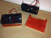
So I have a couple of these fan-cooled copper heatsinks lying around. Brand new; picked them up from the surplus store a few months ago (see pic). Fans are pretty quiet if they're not run at full speed. I have no idea what their rated dissipation is. They're roughly 100mm x 70mm, fins are 12mm tall and the base plate is 5mm thick. What do you guys think: would these be able to keep a hot-rodded ACA from bursting into flames?
So I have a couple of these fan-cooled copper heatsinks lying around. Brand new; picked them up from the surplus store a few months ago (see pic). Fans are pretty quiet if they're not run at full speed. I have no idea what their rated dissipation is. They're roughly 100mm x 70mm, fins are 12mm tall and the base plate is 5mm thick. What do you guys think: would these be able to keep a hot-rodded ACA from bursting into flames?
Attachments
would these be able to keep a hot-rodded ACA from bursting into flames?
The effect of fans too cooling is high, so when accidentally it is off, the effect could be high also

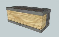
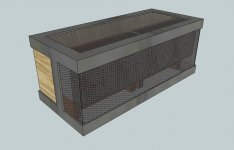
OK, since I got Zen Mod's blessing , I went ahead and Sketchup'd a chassis design. Welded steel, steel mesh, wood. Will be another long-term project due to Maslow's hierarchy of needs, but with any luck it'll be done for BAF16. Then, maybe speakers by BAF17. I'll start a build thread when work commences...
, I went ahead and Sketchup'd a chassis design. Welded steel, steel mesh, wood. Will be another long-term project due to Maslow's hierarchy of needs, but with any luck it'll be done for BAF16. Then, maybe speakers by BAF17. I'll start a build thread when work commences...Attachments
The fans will be automatically controlled, so they shouldn't be accidentally turned off. Of course, that's all dependent on my building skills, so no guarantees
The heatsink looked big enough (and the fan is high quality). If it is small, I will add some kind of protection in case the temperature got too hot due to the fan not working. But if there is speaker protection already, that's not critical.
Hi everybody,
I have a little problem with my ACA build ... My goal is to make a ACA powered by a linear power supply using lt1084. The power supply board is working well giving 22v DC.
Troubles come from the drain setting via 5k pot to get 10v (aiming 11v in this biuld) : I have 0.15v only and turning the pot have no effect :'(.
Instead of using a 2sk170/lsk170, I use a J111 (I take care of the different pin configuration) because I read somewhere it's a possible remplacement and it should do the job well ... it now looks like a big mistake xD.
Can someone confirm that J111 is well working in the ACA (so I'll have the check for another bug) or if I have to order new Jfet (which one ? 2sk170bl on ebay ?) ?
Thanks in advance.
Hi everybody,
I have a little problem with my ACA build ... My goal is to make a ACA powered by a linear power supply using lt1084. The power supply board is working well giving 22v DC.
Troubles come from the drain setting via 5k pot to get 10v (aiming 11v in this biuld) : I have 0.15v only and turning the pot have no effect :'(.
Instead of using a 2sk170/lsk170, I use a J111 (I take care of the different pin configuration) because I read somewhere it's a possible remplacement and it should do the job well ... it now looks like a big mistake xD.
Can someone confirm that J111 is well working in the ACA (so I'll have the check for another bug) or if I have to order new Jfet (which one ? 2sk170bl on ebay ?) ?
Thanks in advance.
Either some part is bad or miss wiring. Check everything again.
Hi everybody,
Instead of using a 2sk170/lsk170, I use a J111 (I take care of the different pin configuration) because I read somewhere it's a possible remplacement and it should do the job well ... it now looks like a big mistake xD.
Can someone confirm that J111 is well working in the ACA (so I'll have the check for another bug) or if I have to order new Jfet (which one ? 2sk170bl on ebay ?) ?
Thanks in advance.
See here from NP himself.
http://www.diyaudio.com/forums/pass-labs/215392-amp-camp-amp-aca-89.html#post3431856
BR,
Eric
A big "Thank You" to Nelson Pass for this design. I'm a rank beginner, but in a surge of "can-do" naivete, I soldered it all together without benefit of the PCB from the store. I'm proud to say that I have two channels built by hand, and they both work!
As a beginner, though, I'm confused by P1. I don't understand how it works. At steady state, with no input, it seems to me that there is no current passing through R10. My multimeter shows the identical voltages on either side. So, at steady state, why doesn't P1 simply turn into a 5K resistance to ground?
Thanks for your patience.
Dean
A big "Thank You" to Nelson Pass for this design. I'm a rank beginner, but in a surge of "can-do" naivete, I soldered it all together without benefit of the PCB from the store. I'm proud to say that I have two channels built by hand, and they both work!
As a beginner, though, I'm confused by P1. I don't understand how it works. At steady state, with no input, it seems to me that there is no current passing through R10. My multimeter shows the identical voltages on either side. So, at steady state, why doesn't P1 simply turn into a 5K resistance to ground?
Thanks for your patience.
Dean
With P1 you should set output voltage (before output capacitor) to half of your power supply voltage. If you are using 19V, set output voltage to cca 10V.
Hi all,
@ e_fortier / Eric : thanks a lot =).
Checking my pcb (=ACA initial schematic) to the DIYstore one (same as PCB drawing in the initial article) and something looks strange about P1.
Schema's P1 go to Q1+R3+R4 and PCB's P1 go to R1+R2+R3+R4
With one is the good one ?
@ e_fortier / Eric : thanks a lot =).
Checking my pcb (=ACA initial schematic) to the DIYstore one (same as PCB drawing in the initial article) and something looks strange about P1.
Schema's P1 go to Q1+R3+R4 and PCB's P1 go to R1+R2+R3+R4
With one is the good one ?
An externally hosted image should be here but it was not working when we last tested it.
An externally hosted image should be here but it was not working when we last tested it.
Yes, you are right. PCB from Nelson Pass connects P1 directly to output capacitor, but on the schematics it goes through R3 and R4 resistors. In reality it doesn't matter, because there is only 0.5V difference across R3 and R4 resistors and P1 is there to set just voltage before output capacitor to half voltage of power supply used.
I guess I was unclear.With P1 you should set output voltage (before output capacitor) to half of your power supply voltage. If you are using 19V, set output voltage to cca 10V.
I want to understand how the circuit operates. Why does a change in P1 alter the voltage on the Q1 drain?
P1 is to set voltage at JFET input using voltage divider mechanism. You can connect P1 between ground and any voltage point, but better to a clean voltage.
The bootstrap is probably more precise if connected to the output, but the ZTX requires some Vbe drop to operate, so may be that's the reason it was not connected to the output but to a lower voltage??
The bootstrap is probably more precise if connected to the output, but the ZTX requires some Vbe drop to operate, so may be that's the reason it was not connected to the output but to a lower voltage??
- Home
- Amplifiers
- Pass Labs
- Amp Camp Amp - ACA