To all S03 users:
If you are using it with BBB (via the BBB-DSD board) the stable Botic release is V3.2 There are V4 and V5 Botic also but I am not sure if there are any sonic benefits of these upgrades other than power management improvements. FYI, the power management is already taken care of by the BBB-DSD board and performs safe and reliable shutdown as well as power sequencing/battery switchover regardless of which version of Botic you are using. Works even if Botic/BBB is 'hung-up' especially if network drive is used.
Thanks Acko. I've been on V4 for a few weeks and it hasn't given any problems. Didn't notice any SQ changes.
Ray
Don’t know if these questions have been asked yet… probably in some form or another...
Just want to double check before I go buying parts for my S03 board. My plan is to use a 3V3 external supply via a Reflektor D. Thus, do I just supply 3V3 to J2 and J4? Then a 5v supply to J3?
What is +VIN2 on the schematic?
Do I need to cut trace between R3 and R13 if I end up only using Div/2?
Also, if using 45/49 clocks for EXT CLK in conjunction with BBB, can I use Turbo MCK instead of the /2 or /4 dividers? If that’s the case then I don’t need U5 and related parts. I guess I can presume that I’d only be using U8 for CLK SEL then. Unless there is a way to bypass U8 altogether and go from SEL to R7 directly.
Thoughts on pros and cons of methods used would be appreciated.
It turns out I was using an earlier version of the BoM and support PDF from when I got the first version of the S03. Just got the most current version and it doesn't have this extra part, so I'll move forward with the newer document.
Also, I'm going to move forward and build out the unit with /2 divider and Turbo MCK so I can choose between both for the BBB. I'm thinking there's no reason why either method wouldn't work.
Also, I'm going to move forward and build out the unit with /2 divider and Turbo MCK so I can choose between both for the BBB. I'm thinking there's no reason why either method wouldn't work.
It turns out I was using an earlier version of the BoM and support PDF from when I got the first version of the S03. Just got the most current version and it doesn't have this extra part, so I'll move forward with the newer document.
Also, I'm going to move forward and build out the unit with /2 divider and Turbo MCK so I can choose between both for the BBB. I'm thinking there's no reason why either method wouldn't work.
Except that Turbo MCK is the clean side of the isolators so if you use that you will be defeating the isolation.
NDK powerpin noise
Hello Acko,
replacement NDKs arrived on dec. 31.2014. and I didn't have the time to solder them and the rest of parts until today.
Anyway, I have the scope and measured voltage on active NDK (90MHz) power pin gives me 300mVpp. I've removed ground wire with alligator clip and using ground spring.
Is this to much?
Yes, External 3v3 to J2 and J4 (Do not mount U12). 5V to J3 - and no links K1, K2, K3, No need to populate clock power section. I you wish remove U4 also (or do not mount U4) and link direct to Ext 3.3V on J3...
...My plan is to use a 3V3 external supply via a Reflektor D. Thus, do I just supply 3V3 to J2 and J4? Then a 5v supply to J3?
Denotes 5V, (shown separately from the clock power). Also replicated for U12 (not shown)What is +VIN2 on the schematic?
Not necessary but best to shutdown this switching section if Div/4 not used.Do I need to cut trace between R3 and R13 if I end up only using Div/2?
Last edited:
...
Anyway, I have the scope and measured voltage on active NDK (90MHz) power pin gives me 300mVpp. I've removed ground wire with alligator clip and using ground spring.
Is this to much?
How is the XO powered? What is the dc voltage on the 3.3V power going into the device. Any pic of your setup?
For S03 I'm using 3 separate secondaries from 2 transformers so every section has it's own power supply. 5v for clock power comes from TPA Placid HD and on board LTC6655 with ceramic capacitor on output, for reclocking and buffer/divider from DIYinHK dual power TPS7A4700 and ADP150 onboard.
Power ripple is even worse on potato buffer, measured directly on power pin gives me 560mVpp.
Power ripple is even worse on potato buffer, measured directly on power pin gives me 560mVpp.
For S03 I'm using 3 separate secondaries from 2 transformers so every section has it's own power supply. 5v for clock power comes from TPA Placid HD and on board LTC6655 with ceramic capacitor on output, for reclocking and buffer/divider from DIYinHK dual power TPS7A4700 and ADP150 onboard.
Power ripple is even worse on potato buffer, measured directly on power pin gives me 560mVpp.
There is bound to be some switching noise especially going up to 90MHz - transient response of the regulator. See whether adding a larger ceramic cap ( in parallel) on the output of the ADP150 reduces this noise. Also larger cap on the power pin of the buffer IC
Can you get a scope capture of the output at 'Turbo MCK' (d.c.) and compare with this BCK to see if there is jitter.
Have you tried sound checks?
Last edited:
@Miksi,
I did some quick tests and saw only < 20mV p-p switching noise on the clock or output 3.3V power lines. My scope BW is 100M only, so tests were done with 25M clocks. The above results are well within device specs for the on-board regulators scaled accordingly. Most manufacturers test @10khz switching whereas the S03 is doing higher than 20MHz! The switching noise can be reduced further with additional bypass/filtering but it is the rising edges that matter most in this case and should be clean and sharp. The slight noise or ringing at the top is harmless.
Again, with the limitation of my scope I cannot see nice switching waveforms of the signals at these frequencies - needs 300 or 500MHz scope to capture fully but all being well the board is functioning correctly.
Last edited:


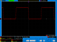
I repeat the same tests to my 100MHz oscilloscope (full BW), no any termination at the end of probes.
Persist mode = 5sec
Sampling playing file = 44.1KHz
I have two Crystek clocks (45+/49+) on S03.
I can't reproduce the miksi's finds.
Persist mode = 5sec
Sampling playing file = 44.1KHz
I have two Crystek clocks (45+/49+) on S03.
I can't reproduce the miksi's finds.
Attachments


I'll have to check, but I think buffered clock edges coincide with bck and partly lrck and this results in uncertanity of reclocked signals. Simple way to resolve this might be to delay clock signal by adding some resistance and I will try this. Is there any benefit in using thin film smd resistors in this case because I only have some 22 ohms? Thin film are unavailable here and acquiring these at Farnell or any other place is justified only within some bigger parts list.
Should not be the case if you look at the timing diagram as shown in the user's guide. Outputs should 'lock' nicely with clean edges to the reference clock (RCK)...
but I think buffered clock edges coincide with bck and partly lrck and this results in uncertanity of reclocked signals.
....
@Lemon, thanks for the plots. So 100MHz is good enough for checking I2S signals. I think I have to tune my probes as the outputs were clean but skewed like sawtooth waveforms. Anyway I also did multimeter checks and found the d.c average ~1.62V which means nearly perfect switching from rail-rail 3.3V swing.
R2 can be changed to delay accordingly but may also affect the rise time for edge triggering of the FFs...
Simple way to resolve this might be to delay clock signal by adding some resistance and I will try this. Is there any benefit in using thin film smd resistors in this case because I only have some 22 ohms? Thin film are unavailable here and acquiring these at Farnell or any other place is justified only within some bigger parts list.
Last edited:
Lemon,
your test looks almost perfect. Maybe 90/98 clocks are not the best solution. Also I have default firmare on Amanero, I didn't tried latest cpld and cpu editions.
Should not use default fw (Amanero in master mode)
Amanero should be slaved to the S03
This could be the cause of your problems
I have users with 90/98 clocks and reported sounding really good!
- Status
- This old topic is closed. If you want to reopen this topic, contact a moderator using the "Report Post" button.
- Home
- Group Buys
- Amanero Isolator/Reclocker GB