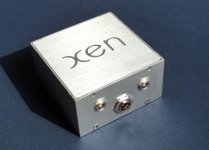
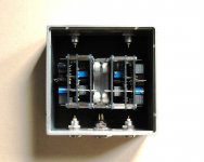
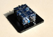
Mr. Evil,
of course I meant the preamp.
But, can we really speak of open loop here? do R4, C1 and R8, C2 not apply some feed back, since any output in a transistor is an input as well?
@Jocko Homo:
well, that sounds interesting. A while ago, you posted a circuit from the MAT02 datasheet, is that it? Come on, some infos please...
Bernd
Sorry, in case I bore you,
A little Idea: since the folded cascodes are said to be unreached in reproducing trebles, shouldn't it make a perfect first stage for a phono amp where the trebles are at +20dB in respect to 1kHz?
To date, I never tried on, but I may next time I find time to play around a little.
Bernd
A little Idea: since the folded cascodes are said to be unreached in reproducing trebles, shouldn't it make a perfect first stage for a phono amp where the trebles are at +20dB in respect to 1kHz?
To date, I never tried on, but I may next time I find time to play around a little.
Bernd
It's local feedback. Open-loop implies no global feedback, and there is none of that.Noobee said:...But, can we really speak of open loop here? do R4, C1 and R8, C2 not apply some feed back, since any output in a transistor is an input as well?..
Balanced Ouput
If I understand your circuit correctly, the output source follower, driven by the second diff pair, sees power supply noise of the negative rail 1:1 ??
Would this not be an argument to go balanced or at least use a current mirror or as some of you might fancy an output transformer ?
Also the DC offset would drift with the negative rail voltage, e.g. when one were to use batteries ??
Patrick
Re: Balanced Ouput
A balanced output would be great, but is only useful if the following stage has a balanced input.
Change in negative rail voltage would appear directly at the output. AC coupling to the next stage is definitely a good idea.
Negative PSRR is around about zero, yes. It's not a problem if the power supply is well regulated.EUVL said:If I understand your circuit correctly, the output source follower, driven by the second diff pair, sees power supply noise of the negative rail 1:1 ??
Would this not be an argument to go balanced or at least use a current mirror or as some of you might fancy an output transformer ?
Also the DC offset would drift with the negative rail voltage, e.g. when one were to use batteries ??
Patrick
A balanced output would be great, but is only useful if the following stage has a balanced input.
Change in negative rail voltage would appear directly at the output. AC coupling to the next stage is definitely a good idea.
Balanced Output
No matter how much energy one invests in designing the power supply, there are hardly any supply that is both totally noise free (especially at high frequencies) AND voltage stable.
I could not help thinking that a low impedance (meaning therefore high capacity) battery supply, coupled with a servo circuit (using for example another dual JFET) which also serves as a (variable) current source to drive the first diff pair, AND a form of balanced receiver right before the input of the following stage (if singled ended) would improve the performance of this simple and elegant circuit significantly.
And I do not like coupling caps, neither at the input nor at the output.
Patrick
Exact RIAA values
For those who might want exact RIAA values, and if my maths is correct :
C1 = 212n (e.g. 150n // 47n // 15n)
R8 = 1.272k (e.g. 1.24k + 33.2R)
C2 = 2.5n (e.g. 2.2n // 330p)
Philips (or BC Components) does a series of 1% axial PP caps at very reasonable price.
I though find the bias at both diff pairs a bit low, so that one is not really operating at the most linear regime of the JFETs. Probably a fact of 5 to 10 would be better, thermal dissipation allowing. Rs and Cs values need changing of course.
Patrick
Re: Balanced Output
The noise floor of the circuit as it stands is ~80dB down. That's with a cobbled together LM317/337 regulator with little bypassing, very long wires and no shielding.
Well I suppose it depends on how far you're willing to go. As I mentioned earlier, this is something that will see infrequent use, so although I do want it to be as good as possible, there are limits of complexity and cost.EUVL said:No matter how much energy one invests in designing the power supply, there are hardly any supply that is both totally noise free (especially at high frequencies) AND voltage stable.
I could not help thinking that a low impedance (meaning therefore high capacity) battery supply, coupled with a servo circuit (using for example another dual JFET) which also serves as a (variable) current source to drive the first diff pair, AND a form of balanced receiver right before the input of the following stage (if singled ended) would improve the performance of this simple and elegant circuit significantly.
And I do not like coupling caps, neither at the input nor at the output.
Patrick
The noise floor of the circuit as it stands is ~80dB down. That's with a cobbled together LM317/337 regulator with little bypassing, very long wires and no shielding.
Well I suppose it depends on how far you're willing to go. As I mentioned earlier, this is something that will see infrequent use, so although I do want it to be as good as possible, there are limits of complexity and cost.
That is always true, even for the so-called cost no object designs...
But inserting 1-fet currentsources at the two tailes here costs 2 fets and 2 resistors (not that it cannot get much fancier here as you know...)
@Patrick: do you mind to draw a quick sketch of your servo idea?
In AoE there is a conceptual drawing of a LTP with a current mirror (wilson style, if I recall right) as a load (on page 'have-to-look-at-home'), having then a single output, do you think of such a receiver?
I alway wondered why nobody seems to use a dual-diff-pair as MC-Input stage, but that may be too OT here.
Rüdiger
I did say I was thinking of using current sources, but all this discussion of PSRR has made me change my mind: A CCS in the first LTP would significantly improve its negative PSRR, but when the preamp as a whole is considered, it actually makes negative PSRR worse!
Say the negative rail increased in magnitude. This would increase the current through the first LTP, increasing the output voltage and thus increasing the current through the second LTP. This would increase the output voltage, partially cancelling the change in rail voltage. In fact a quick calculation says that this effect gives ~28dB of negative PSRR. With a CCS, the negative PSRR would only be as good as that of the second LTP alone, or 0.
A CCS in the second LTP would have very little effect, and so I don't think it's worth it if I'm not also going to use one in the first LTP.
Finally, the balanced version
Have been planning to build this for a few years now, and finally finishing this week.
Always want to build the balanced version only in order to get round the problem with low PSRR at the top rail.
Changes to the circuit are as follows :
+/-20V rails (battery powered, followered by 3x LM329, LP filtered to drive 5x BC327/337 follower in parallel)
Using 2SJ109 for 1st stage, 2SK389 for 2nd stage
2SJ109 is cascoded by 2x BC560C at -7V base voltage
R1,2,3,9,10 10k (Caddock MK132)
R5 2.5k nominal (2.7k S102//33k Beyschlag, fine trimmed for common mode DC)
Rv1 51R-51R//5k trimpot (for 1st stage differential DC)
R6,7 51R-51R//5k trimpot (for overall differential DC)
R4,C1 2.1k,147n (100n//47n)
R8,C2 880R,3.88n (887R//110k,2.2n//1n//680p)
After trimming, DC at the output before rumble filter is stable to within +/-5mV.
It is surprising stable considering the DC gain of 60dB.
A 10Hz rumble filter (15n/1M) was also added before the output followers, which are 2SK2145GR at 4mA.
The rumble filter will take care of any remaining DC after R9,10.
Gain at 1kHz is measured at 620x, which is as per expectation.
Still some final wiring to do.
Thanks for the nice and simple circuit.
Patrick
.
Attachments
Simplified form.
Patrick
.
Hello Patrick
Thank you for sharing the finalized circuit.
Why did you use the leds on the output buffers ?
What is the vdrop on those leds ?
- Home
- Source & Line
- Analogue Source
- All JFET open-loop RIAA pre-amp


