My turntable has been sitting on a shelf for many years. Finally I have done something about this and designed an RIAA pre-amp. It uses JFETs since I recently bought a load and like them. It has no global feedback partly because it's an integral part of the functioning of the circuit and partly because I never go open-loop and want to do something different for once.
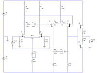
As per the attached schematic it consists of two differential stages each of which implements part of the filter, the first being the pole and zero at 50 and 500Hz, the second being the pole at 2122Hz (with an extra zero at 50kHz as I have seen suggested in a few places). A source-follower buffers the output.
Differential stages use 2SK389/2SJ109, output stage is 2SK170/2SJ74.
It requires some careful pot twiddling to balance the differentials (essential for correct frequency response) and zero offset. The various source degeneration resistors need to be chosen to achieve the desired gain with particular JFETs.
Since I have not listened to vinyl (at home at least) for a few years and have no other pre-amp to compare, I can't really judge how well the circuit performs, but it's certainly not bad.
Attachments
Apparently yes. I wouldn't trust it with a power amp without an input cap, but the offset does seem to remain constant and low even after an hour or so of running. I suppose that using monolithic dual FETs takes care of thermal matching so offset of each pair should remain low, and since the same current flows in both differentials, any change in their offset should be roughly equal and opposite, leaving nothing at the output.analog_sa said:You can actually get stable offset from this circuit?! Looks not bad at all...
Indeed I have. It's just a prototype at the moment, so still room for change. I will probably change R3 for a CCS (JFET, of courseanalog_sa said:...Have you considered adding current sources in the tails?
 ) and possibly also R5, which will give a nice boost to PSRR.
Balanced out
Hallo,
Did anybody think of using it with a balanced pre/amp?
I wonder if it could drive them without the actual complementary stages. Using FET or MOSFET input amps (e.g. Pass or its diy clones) it could succeed.
And with dual FETs only in the circuit the offset will be minimized.
Any thoughts?
Laci
I searched around but couldn't seem to find that one. However it is not an unusual design: I have seen plenty of double-differential JFET amps. The only thing about it that I haven't seen before is the way filtering is accomplished.choky said:reminds me to Hafler preamp........
I relly dunno what number,but it's on their site anyway
Do you think that would be worth it? Those JFETs are already low noise and not cheap. Maybe if I were going no-expense-spared, but this is something that will see only occasional use.jam said:You might be on to something here...........You might want to consider doubling up the fets in the first differential.
Jam
That makes me think of something: Is it better to have n-channel or p-channel for the input? The datasheets say noise is the same for both.
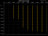
I've attached what the sims say the distortion spectrum at 1kHz should look like. Higher order harmonics are very low, which is nice.
Attachments
I recall borbely opts for npn in his papers (fets-the new frontier in audio), and I think he did for noise reasons (not sure).That makes me think of something: Is it better to have n-channel or p-channel for the input? The datasheets say noise is the same for both.
The only thing about it that I haven't seen before is the way filtering is accomplished.
You may want to visit this thread:
http://www.diyaudio.com/forums/showthread.php?s=&threadid=12397
Rüdiger
I had a quick glance through that paper and could see no explicit statement of which was quietest, but all the examples of low-noise circuits used n-channel inputs, so I think it can be safely assumed that they are the best choice.Onvinyl said:
I recall borbely opts for npn in his papers (fets-the new frontier in audio), and I think he did for noise reasons (not sure)...
Nothing new under the sunOnvinyl said:...You may want to visit this thread:
http://www.diyaudio.com/forums/showthread.php?s=&threadid=12397
I think it's an elegant way of shaping frequency response.How much gain do you need for a MC? My prototype has ~40dB of gain at 1kHZ. If the LTP source resistors were made very small then gain could be increased to 50 or 60dB. Alternatively a third LTP could be added.EUVL said:Nice and Simple Circuit, but enough gain for MC ?..
It would indeed be just the addition of an extra pair of FETs to give it a differential output, which would greatly reduce any possible worries about DC offset stability, enhance PSRR and send even harmonic distortion through the floor. No good for me though, since the rest of my kit is all unbalanced.EUVL said:...And how about making it fully symmetrical with differential output ? Probably not much more needed than adding another source follower on the opposite arm ??.
You're right. The input resistors appear in series, not in parallel.Noobee said:Shouldn't R13 and R14 read around 24k in order to achieve the nominal 47k?
Bernd
It's about +/-1dB from 10Hz-20kHz. I didn't spend any great effort making it accurate, so I'm sure it would be possible to choose component values that can get closer. Note that it's important that the voltages across the LTP load resistors be balanced as much as possible or effective filter component values will change.Onvinyl said:Did you measure the riaa's accuracy? If so, how is it?
Rüdiger
Hi Mr. Evil,
I've found another neat idea of you here: http://www.diyaudio.com/forums/showthread.php?s=&threadid=53548&highlight=
That leads to the first thing that went through my head loooking at your schematics:
What are the reasons you don't use ccs here. Sonics? Lazyness (I guess not?)
Bernd
I've found another neat idea of you here: http://www.diyaudio.com/forums/showthread.php?s=&threadid=53548&highlight=
That leads to the first thing that went through my head loooking at your schematics:
What are the reasons you don't use ccs here. Sonics? Lazyness (I guess not?)
Bernd
I have built several open-loop JFET preamps. Running the input "balanced" makes all the difference in the world. Everyone needs to try that at least once in their DIY career. I used current mirrors in the second stage to convert back to SE, and pick up some dBs in the process.
The uber-nerd that I am..........I trimmed the RIAA to +/- 0.04 dB. Or better.
Jocko
The uber-nerd that I am..........I trimmed the RIAA to +/- 0.04 dB. Or better.
Jocko
But there is a CCS in thereNoobee said:Hi Mr. Evil,
I've found another neat idea of you here: http://www.diyaudio.com/forums/showthread.php?s=&threadid=53548&highlight=
That leads to the first thing that went through my head loooking at your schematics:
What are the reasons you don't use ccs here. Sonics? Lazyness (I guess not?)
Bernd
The four input JFETs, being depletion mode devices, maintain a constant voltage across R10/RV1, giving a constant current.EIT: Or did you mean in the preamp? I haven't used a CCS here for simplicity, since it's still just a prototype. I may use one or two CCSes for the final version.
I considered using a current mirror in the second stage, but how do you control the DC offset?Jocko Homo said:I have built several open-loop JFET preamps. Running the input "balanced" makes all the difference in the world. Everyone needs to try that at least once in their DIY career. I used current mirrors in the second stage to convert back to SE, and pick up some dBs in the process.
The uber-nerd that I am..........I trimmed the RIAA to +/- 0.04 dB. Or better.
Jocko
- Home
- Source & Line
- Analogue Source
- All JFET open-loop RIAA pre-amp