I did and that impedance is right for one 46, IHMO. The LL1692 is among the few Lundahl's I like and capable of good frequency response up to 70 KHz.
You can try 320V/30mA getting about 1.8W into 8R and 2W into 6R (minus transformer losses). Class A1 and about 82V peak-to-peak drive.
If you should like this it would be better having the LL1692 with a smaller gap for 30-35mA with about 50-55H inductance.
You can try 320V/30mA getting about 1.8W into 8R and 2W into 6R (minus transformer losses). Class A1 and about 82V peak-to-peak drive.
If you should like this it would be better having the LL1692 with a smaller gap for 30-35mA with about 50-55H inductance.
Last edited:
Thanks to everyone who helped. The amp is built (left monoblock anyway) and the relay works perfectly. Once the bias circuit comes up to voltage the relay closes, the main rectifier heaters engage and the 45 B+ kicks in. Pull the EZ81 rectifier for the bias and the main rectifier immediately cuts out. I'll make a note to regularly check that it disengages quickly.
good to hear
")
I have amps using this circuit from 20 years ago, and all is good.
This valve rectified LC approach sounded much nicer than the SS versions I used previously, and I have stuck with it since then. In my experience the NOS EZ81 vales available have been more reliable than modern 300Bs, so failed bias supply has not been a major issue.
 Commenting on moderation is a violation of forum rules.
 Ignorance of the rules which are posted is not an excuse for the repeated violation of forum rules.
Questions or comments should be directed to moderation either by PM (to the mod of your choice) or by using the forum's report system.
...
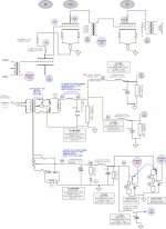
So I finally got around to turning my pencil sketch ideas into something resembling a usable circuit diagram, which I've attached seeking comments and inputs. Brief description of the design choices and reasons.
What started out with the objective of simplifying the signal circuit has overcomplicated the PSU - perhaps that's an inevitable consequence. I may also be overdoing the smoothing.
So I finally got around to turning my pencil sketch ideas into something resembling a usable circuit diagram, which I've attached seeking comments and inputs. Brief description of the design choices and reasons.
- as far as possible use tube regulation and LCLC filtering
- all DHT valves in signal circuit
- 26 DC coupled to 71A, IT coupled to 45
- Avoid the large cathode resistor and bypass cap on the 71A by grounding the cathode
- Set the 26 anode to -27V to correctly bias the 71A
- Fixed bias for both 26 and 45
- Negative voltage rail serving both the bias trimmers
- -ve rail also sets the 26 cathode voltage, isolated by a further LC filter from the bias trimmers
- Protect valves from loss of bias (just realised I haven't yet protected the 71A)
What started out with the objective of simplifying the signal circuit has overcomplicated the PSU - perhaps that's an inevitable consequence. I may also be overdoing the smoothing.
Attachments
Hi!
I am counting 6 capacitors in the signal path. That could be reduced further and even without negative voltage supplies.
You did not show the filament PSUs which will also be very relevant. There are cathode resistors shown for the 71A and 45 but without value. What is their purpose? Measurement of current?
BR
Thomas
Thanks Thomas - the DHT cathodes are 22R pairs to a 10R sensing resistor and you're right I forgot to label them.
I don't know if it's terminology or my misunderstanding. There are caps in the PSU, but not what I call the signal path ? Those caps are there as part of LC smoothing filters - I don't think I can remove them without reducing the ripple filtering ?
I am beginning to think though that in trying to avoid the 71A cathode bypass cap I've overcomplicated the design. Is it worth pursuing this path or should I simplify ?
Hi!
It is a common misunderstanding that a transformer coupled stage does not have any capacitors in the signal path. The signal travels in loops. For example at the output stage: plate of 45 to primary of OPT, from there through the last cap in the PSU to ground and from there through the sensing and equalisation resistors to the the 45. This last cap is fully in the signal path and is sonically very relevant as it transfers power.
Similar situation at the input side: interstage secondary transformer to grid from cathode through the dame resistor5s and the last cap in the bias supply back to the secondary of IT. This cap hardly transfers any power and is sonically less relevant IME but still in the signal path
BR
Thomas
I don't know if it's terminology or my misunderstanding. There are caps in the PSU, but not what I call the signal path ?
It is a common misunderstanding that a transformer coupled stage does not have any capacitors in the signal path. The signal travels in loops. For example at the output stage: plate of 45 to primary of OPT, from there through the last cap in the PSU to ground and from there through the sensing and equalisation resistors to the the 45. This last cap is fully in the signal path and is sonically very relevant as it transfers power.
Similar situation at the input side: interstage secondary transformer to grid from cathode through the dame resistor5s and the last cap in the bias supply back to the secondary of IT. This cap hardly transfers any power and is sonically less relevant IME but still in the signal path
You are right they are needed, not only for smoothing but also to close the signal loopThose caps are there as part of LC smoothing filters - I don't think I can remove them without reducing the ripple filtering ?
If your objective was to reduce the caps in the signal path, you can achieve the same result with conventional methods which eases the power supply and avoids the negative railI am beginning to think though that in trying to avoid the 71A cathode bypass cap I've overcomplicated the design. Is it worth pursuing this path or should I simplify ?
BR
Thomas
Thanks Thomas. I know my understanding is at an early stage, I've only recently moved to thinking more about current flows than voltage differences. Every bit of advice I get helps, so thanks.
I've been trying to avoid using constant current sources and voltage regulators, trying to keep the design purely passive and iron-based (because in my experience that's what sounds best). However I'm open to suggestions and in fact have ordered Rod Coleman filament regulators, for the 26 to begin with.
I recently built a pair of amps (which now live at my brothers and are giving the best sound I've ever heard) which were very simple 5842 IT coupled to 45. Tribute IT and OPT, fixed bias on the 45. Based on an SJS design (thanks). 2 positive PSU rails and 1 negative for the fixed bias, all LCLC filtered. I was going to simply build a set of those for myself, but decided to explore the "all-DHT" sound for myself first.
Let's go back to the primary question first - is the concept of using the negative rail for the 26 PSU, to land the DC coupling to the 71A at -27V, valid ? Is it valid to then apply the 26 bias of -172V via the secondary of the input transformer ?
This is a lot of hassle for a #45 amp. Use your low source impedance to drive a SUT (maybe one of the common 600:15K transformers available). Assuming you have an active preamp, you'll get about half the driver voltage gain you need there and you can just do a #26 directly coupled to a 45 with no interstage transformer.
I also believe this would sound better.
I'm glad you've come around on where the signal path actually goes, as making expensive design choices on false assumptions is no way to start your build.
I also believe this would sound better.
I'm glad you've come around on where the signal path actually goes, as making expensive design choices on false assumptions is no way to start your build.
Let's go back to the primary question first - is the concept of using the negative rail for the 26 PSU, to land the DC coupling to the 71A at -27V, valid ? Is it valid to then apply the 26 bias of -172V via the secondary of the input transformer ?
Yes it is valid given you take care of potential bias loss issues for the 71A, also the input transformer should be isolated for that voltage. 170V should not be an issue but check.
What I wanted to point out that you will have the same number of caps in the signal path (and I understand that is one of your concerns) by going conventional, LC couple the 26 and use cathode bias on each stage. You can even reduce the number of caps by applying ultrapath caps.
So you plan too use AC on the 71A? Might bet tricky to null out residual hum with AC on the driver filaments
BR
Thomas
LC coupling 26 to 71A might be a good idea thanks. All getting a bit complex - maybe this design is something to try later.
I haven't used any filament regulators before so was planning to start with the 26, but yes I plan to use them for the 71A too, possibly even the 45.
I haven't used any filament regulators before so was planning to start with the 26, but yes I plan to use them for the 71A too, possibly even the 45.
This might help re. current loops?
ETF Presentation
There's a lot to be said for starting simple and get the amp up and running, then experiment. Perhaps start with RC or LC coupling, though if you need to buy PS iron that can be a bit inconvenient. Just a suggestion.
3 stage DHT amps can be ruthless at exposing hum from filaments - the 26 should be fine as you're using Rod's regs, the 71A is only 5V @ 0.25A so might be okay with AC - the 10Y I use is 7.5V @ 1.25A and I had to use DC, just couldn't get it quiet with AC. I agree with Thomas, AC could be tricky.
Last edited:
Hi RhythMick,
If I were to built a 26-71-45 amp, I would use Ale's gyrator for the 26 , 26 in filament bias using Coleman regulator, cap coupled to the 71, 71 self-biased with ultrapath and IT coupled to the 45. 45 self biased and ultrapath. You need to use a RC or shunt regulator to drop voltage for the 26-71.
I've played with this setup in the past, and for a 3 stage, all DHT amp it sounds very good.
You can also DC couple 26-gyrator mu out to the 71, and you might find the operating points so you don't need to drop the B+.
Anyway, as Thomas said, there is no free lunch in trying to minimize the number of capacitors in the signal loops/path.
Cheers,
Radu
This might help re. current loops?
ETF Presentation
There's a lot to be said for starting simple and get the amp up and running, then experiment. Perhaps start with RC or LC coupling, though if you need to buy PS iron that can be a bit inconvenient. Just a suggestion.
3 stage DHT amps can be ruthless at exposing hum from filaments - the 26 should be fine as you're using Rod's regs, the 71A is only 5V @ 0.25A so might be okay with AC - the 10Y I use is 7.5V @ 1.25A and I had to use DC, just couldn't get it quiet with AC. I agree with Thomas, AC could be tricky.
That article is very interesting, thanks for that Simon. Bookmarked, as I think it's one of those to go back to repeatedly. One immediate impact though is that I'm going to start drawing my circuits showing the current loops like that, with the final PSU cap in there.
Parafeed looks interesting, I've been glancing at it repeatedly out of the corner of my eye for a few months. It feels like an advanced topic that would be the equivalent of running before walking. Time to leave the pencil behind for a bit and get the build done, starting simple then "improving" to hear the difference in sound (and gain the experience).
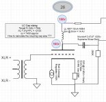
Thomas or others, could you help me get my head around how to calculate the capacitor value for the LC coupling ? I've attached the start of a diagram for a simplified amp : 26 LC coupled to 71A.
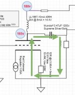
Rather than find a formula, I want to try and understand it from first principles. The second picture shows how I think the amplified signal flows to the grid of the 71A - again do I have this basic grasp right ?
The Choke reactance formula I know : XL = 2*pi*F*L, so at (say) 5Hz its 12723
Capacitor reactance formula is : XC = 1/(2*pi*F*C). If I set these equal and solve for C = 12723 / (2*pi*5*12723) this gives 2.5uF?
Perhaps the capacitor reactance should be set equal to the choke reactance in parallel with the 26 rp (estimated at 7400 at 165 plate).
I feel like I'm getting close to understanding parts, but putting the whole together wrongly. Someone put me on the right path please ?
Attachments
Last edited:
This formula doesn't take the 200k (chosen arbitrarily) 71A grid resistor. This link
https://www.tubecad.com/2014/09/blog0308.htm
gives a formula of 159155/(F*(rp + Rload), which gives 0.15uF for 5Hz. The formula is for a different circuit so may not be relevant.
https://www.tubecad.com/2014/09/blog0308.htm
gives a formula of 159155/(F*(rp + Rload), which gives 0.15uF for 5Hz. The formula is for a different circuit so may not be relevant.
Sorry for the multiple posts ... I think I'm getting there. Would appreciate a quick confirmation if I now have this right.
This article is nice and clear ...
http://circuitcellar.com/wp-content/uploads/2012/04/Honeycutt-AXapril2012.pdf
C = 1/2*pi*f*(Rs + Rg)
where...
Rg is the grid resistor
Rs is the source impedance = rp*Rp / (rp + Rp)
rp is the source valve plate resistance
Rp is the source valve plate load.
With a choke, Rp is presumably the choke inductive reactance, ie 2*pi*f*L. So I can plug that into the above formula or more usefully perhaps into a spreadsheet.
Using
rp = 7400
Rg = 200000
L = 405
I calculate the following cap requirements to set the -3db corner at these frequencies ...
F C
1 0.79uF
2 0.39uF
3 0.26uF
4 0.19uF
5 0.16uF
- Status
- This old topic is closed. If you want to reopen this topic, contact a moderator using the "Report Post" button.
- Home
- Amplifiers
- Tubes / Valves
- All DHT Circuit Advice