The relay trigger will be taken off a separate bypass leg (not the trimmer stack ) and it will engage / disengage the 5v heaters on the main rectifier. That way I should get both a slow start and a cutout if the bias fails. The relay itself will be located near to the mains transformer but underneath so not right next to it. I figure any noise introduced there has a much bigger chance of being smoothed.
You'll still have B+ on the relay, right? Why not break the primary AC and just kill the amp instead of leaving other circuits energized?
You'll still have B+ on the relay, right? Why not break the primary AC and just kill the amp instead of leaving other circuits energized?
Sorry I'm missing something. How would the bias ever get power if the mains primary requires the relay to be energised by the bias?
Yes the relay will still see c+ voltage and has been chosen for it (400vac switching)
Sorry I'm missing something. How would the bias ever get power if the mains primary requires the relay to be energised by the bias?
Yes the relay will still see c+ voltage and has been chosen for it (400vac switching)
See post #5 for the startup method. This has to energize an instant ON bias supply, though. But I think you decided that was the best type to build into the amp. Also, there is a difference between a VAC and VDC rating because of the AC 0v crossing in the cycle that doesn't happen in DC current.
Last edited:
FYI - this is the relay I ordered.
40.52.7.024.0000 | Finder DPDT PCB Mount Non-Latching Relay, 24V dc Coil | Finder
Coil resistance is 1k2, so I plan to have a 6k resistor above it give approx 20V. The coil should engage above about 16V and disengage below 3V ish.
The N/O contacts (DPDT) will be used to engage the 5V heaters for the 5R4WGB, which will have rectified but unsmoothed voltage on them at 300V. Maximum switching voltage is 400VAC.
Thanks to everyone who helped. The amp is built (left monoblock anyway) and the relay works perfectly. Once the bias circuit comes up to voltage the relay closes, the main rectifier heaters engage and the 45 B+ kicks in. Pull the EZ81 rectifier for the bias and the main rectifier immediately cuts out. I'll make a note to regularly check that it disengages quickly.
Calculation of LC filters using Lundahl chokes in CMR
Hi all. Many Lundahl chokes (eg LL1673-20H) have 2 coils and a CMR mode where one coil is in the power rail and one in the ground return.
When using the 2nd order filter equation, should I use the total inductance of both coils or just one? I'm assuming both, just checking.
Hi all. Many Lundahl chokes (eg LL1673-20H) have 2 coils and a CMR mode where one coil is in the power rail and one in the ground return.
When using the 2nd order filter equation, should I use the total inductance of both coils or just one? I'm assuming both, just checking.
Be aware that there are two ways of wiring the choke into both rails. One is as a common-mode choke, which may suppress noise but does little smoothing of ripple. The other gives the full choke inductance for smoothing, but will not do much noise suppression. People often get these two mixed up, so say they are using a common-mode choke when they are actually using it in series-aiding mode.
Assuming you want ripple reduction then you use the total choke inductance, which will be roughly four times the inductance of a single winding (or the two in parallel).
Assuming you want ripple reduction then you use the total choke inductance, which will be roughly four times the inductance of a single winding (or the two in parallel).
So this from the Lundahl datasheet for the LL1673-20H.
Planning on using the CMR mode, at the bottom labelled "serial mode for improved common mode rejection". I believe this will give me the full 20H for smoothing, even though 1 of the coils is in the ground leg. Is that correct? So 20H with a 200uF cap will have a cutoff - 3db at 2.5Hz for example.
I also believe that the + rail will see a Vdrop of 30R x 66mA = 2V, while the local ground (before the return coil) will be lifted to 2V. Is that correct?
Attachments
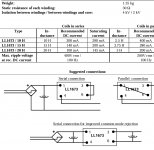
Yes, that 'CMR' connection gives you the full inductance for smoothing and just a little inductance for common-mode rejection. For the sake of clarity, this is the connection which some people call 'common-mode' but it does not use the choke as a common-mode choke.
Many thanks for confirming
Tuning capacitors before LCLC filters
Imagine a simple PSU design
400-0-400 -> 5U4GB -> LC filter
L = 10H, C = 200uF. Expecting about 66mA current total (split across 3 valves, each of which will have an LC filter taken from the main shared filter).
Expecting voltage drop across the 5U4GB (50V ish) taking it to 350V before the filter. About 10% loss across the LC filter, so about 315V at the top of the cap. I then have DCR losses to take into account. Let's say I'd ideally like to get about another 30V at the top of the first cap.
Though I don't seem to be able to find it now, I'm sure I've read that a small tuning cap before the LC filter will increase that voltage, without sacrificing all the benefits of this being a choke input filter design. Is that correct ? How does one work out the value needed to try it, or is it a case of trial and error ?
Though I don't seem to be able to find it now, I'm sure I've read that a small tuning cap before the LC filter will increase that voltage, without sacrificing all the benefits of this being a choke input filter design. Is that correct ? How does one work out the value needed to try it, or is it a case of trial and error ?
If you employ any cap before the choke that is sufficiently large so as to increase your voltage out of the LC filter appreciably, you no longer have a choke input filter, and you are moving toward a pi filter. That being said, you won't need much of a cap to get 30 more volts, so have at it, and you'll still have much of the choke input advantage. You could do trial and error, but start with maybe 1.5uf and go from there. Or, you could always plug your values into Duncan's power supply design software and get pretty close right away.
Depends what you call sacrifice: something that's sure to be jettisoned is the internal resistance: with an input cap of any value, the no-load output voltage will tend to Vin peak.Though I don't seem to be able to find it now, I'm sure I've read that a small tuning cap before the LC filter will increase that voltage, without sacrificing all the benefits of this being a choke input filter design. ?
Depending on the cap value, this voltage will fall more or less quickly with current, depending on the cap value.
This means that you will to balance the cap value to the expected quiescent current, hoping that it will remain stable.
Note that this cap will be severely stressed, and you should use a PP type rated at at least 1kV.
Value will be in the tens to hundreds of nF, perhaps 1µF if the current required is large. You will have to experiment
Putting a small cap at the input of a 'choke input' PSU will raise the output voltage, but it will also almost certainly raise the output impedance too. I suspect that the popularity of this tweak is because it degrades the sound of zero-feedback amplifiers (by introducing subsonic supply rail wobbles) but for some people any audible change caused by a move away from conventional engineering must be an improvement.
Clarify cathode bypass for DC coupled tube
I've not built a DC coupled design before so just want a little clarification and sense checking please.
I'm building an ALL-DHT power amp.
26 direct to 71A, interstage to 45.
For the 71A, the cathode will be elevated obviously. I'm currently thinking the resistors under the cathode should be separated.
R1 would lift the local ground
R2 would provide the bias
R2 would be bypassed.
Is that correct?
Any option to avoid that cathode bypass cap?
Circuit?
As a general rule, using DC coupling and a large bypassed cathode resistor means swapping a small problem for a slightly bigger problem. You lose a coupling cap (and associated high pass filter) but gain a decoupling cap (and a big frequency shelf). Typically, coupling caps (being film) do less harm than cathode decouplers (being electrolytic). The shelf looks very much like a high pass so you still get phase shift. You also get less headroom as the elevated cathode has used up some of the supply rail voltage.
As a general rule, using DC coupling and a large bypassed cathode resistor means swapping a small problem for a slightly bigger problem. You lose a coupling cap (and associated high pass filter) but gain a decoupling cap (and a big frequency shelf). Typically, coupling caps (being film) do less harm than cathode decouplers (being electrolytic). The shelf looks very much like a high pass so you still get phase shift. You also get less headroom as the elevated cathode has used up some of the supply rail voltage.
- Status
- This old topic is closed. If you want to reopen this topic, contact a moderator using the "Report Post" button.
- Home
- Amplifiers
- Tubes / Valves
- All DHT Circuit Advice