He can use film capacitors for cathode bypass. Being DC coupled voltage rating can't be too small. 400V/100uF is not a problem, is infinitely better than electrolytics and is reasonably priced like the Solen/SCR types. As the 71a is low gm 100 uF should enough to get cut-off around 3 Hz....
Swapping, say, 0.47uF (coupling) for 100uF (decoupling) still seems somewhat pointless. For all practical purposes the stage is still AC coupled. You just have DC coupling at very low frequencies so bias shifts in one stage affect the next one too.
It depends.
Your problem is the you only argue with everyone without doing anything practical to support your claims!
Nothing practical here, without any schematicIt depends.
Your problem is the you only argue with everyone without doing anything practical to support your claims!

Mona
His "claims" as you put it are consistent with good engineering practice, and I have designed and tested such an amplifier. It proved to be highly sensitive to the quality of the cathode bypass capacitor, a small high quality film capacitor would certainly be easier to find, and exert less (non ideal) influence on circuit performance assuming of course that the succeeding stage was fixed biased and therefore required no cathode bypass capacitor.
In a case where there are no provisions for fixed bias and a cathode bypass capacitor would be used anyway I would elect as the OP did to direct couple and eliminate one of the two LF poles. DC stability has not ever proven to be an issue in anything I have designed.
(6SN7 driving 2A3 for example)
Just be aware that the cathode bypass cap will most definitely contribute in possibly undesirable ways to the overall performance of the circuit depending on the part chosen.
Might want to look at some of Jack Elliano's (Electra-Print) ideas as well. Electra-Print.com 300B DRD Audio Tube Amplifier for example.
a small high quality film capacitor would certainly be easier to find,
The Solen capacitors in the 400V ratings are rather easy to find. The 250V a bit less but still nothing to worry about. The cost for the 100 uF is about $20-25. In Europe there are the SCR (the original manufacturer) that can be even cheaper. You buy it and you will never have to replace it. Paralleling caps is not good practice in my experience, sometimes worse than not paralleling at all.
I'm not a fan of solen capacitors much preferring ASC and Clarity for large value films. Apparently you have not run into the early Solen fast caps that all failed over time. (Something to do with the metalized film deteriorating to the point that the capacitors no longer had measurable capacitance.) I hate to admit it but I don't really like the way they sound when audio currents are coupled through them, this is anecdotal because I have no recent measured technical reason to base this preference on, maybe just one of my superstitions.
Like you I've had mixed results paralleling film capacitors and tend to avoid it, there have been combinations that worked really well and ones equally that didn't. I don't do it in the direct signal path. I have paralleled identical film capacitors in PSU applications with good results
Like you I've had mixed results paralleling film capacitors and tend to avoid it, there have been combinations that worked really well and ones equally that didn't. I don't do it in the direct signal path. I have paralleled identical film capacitors in PSU applications with good results
If he has an CCS at the anode, decoupling the cathode is useless
Mona
From a noise performance and potentially distortion performance standpoint that is not always true. (SY wrote about this extensively and in some limited testing I did with DN2540 cascode CCS I found there were measurable differences in both noise and distortion, I believe this was due in both cases to the substantial increase in rp, and the tube amplifying the johnson noise in the cathode resistor.
As always lots of good input and I thank everyone for contributing. That's how I learn.
I have good quality coupling caps ready to use, if that's a better option. Mundorf Silver/Gold 0.22uF and 0.47uF. I was trying to eliminate the caps by DC coupling, but as DF96 says if I'm just swapping one problem for a bigger one then maybe it's not the way to go. The amp will have a separate negative bias PSU and the 26 and 45 will have fixed bias, so it's ZERO trouble to make the 71A fixed bias too.
I figure I should just try both and decide which I like best.
My question still stands though. IF I go with DC coupling, should the cathode bypass cap bypass ONLY R2 in my example, or should it go to ground (0v) ?
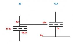
"Ground" gets a little complex in my schematic (and I apologise for not having a schematic yet, but work went a little crazy last few days). I don't have any CCS in my circuit, it's pure tube rectifiers, chokes, caps, tubes and resistors. Oh and transformers (Tribute). The chokes are going to be Lundahl - I haven't used them before but plan to use them in CMR mode, so 1coil in the top rail and 1 coil in the "ground" return. So for example the LL1672-20H will provide the initial shared LC, with the power from there going to the 3 valve PSU rails via a further LC for each. I plan to use the LL1667-25 for the 26 and 71A. With around 16mA through the 71A, the 1k2 coil in the ground return will raise the 71A ground roughly 19V above the common ground return point which is itself 2V above earth reference ground. Matching the 71A cathode with the bias from the 26 to get the right bias needs a fair bit of thinking through, but I think I have it about right now. The cathode bypass cap under the 71A could go to;
a) junction of R1/R2 - so only bypassing the final 27V of the cathode voltage
b) local 71A ground, ie before the 1k2 return coil of the LL1667-25
c) 0v earth reference
I initially figured it should go to 71A local ground, but the 1k2 coil forms part of the resistance which is raising the 71A cathode so if I don't bypass it the varying current in the 71A will vary the cathode voltage. So I THINK that bypass cap should go to 0v.
Again - I can just try them, but looking for advice and to improve my understanding.
I have good quality coupling caps ready to use, if that's a better option. Mundorf Silver/Gold 0.22uF and 0.47uF. I was trying to eliminate the caps by DC coupling, but as DF96 says if I'm just swapping one problem for a bigger one then maybe it's not the way to go. The amp will have a separate negative bias PSU and the 26 and 45 will have fixed bias, so it's ZERO trouble to make the 71A fixed bias too.
I figure I should just try both and decide which I like best.
My question still stands though. IF I go with DC coupling, should the cathode bypass cap bypass ONLY R2 in my example, or should it go to ground (0v) ?
"Ground" gets a little complex in my schematic (and I apologise for not having a schematic yet, but work went a little crazy last few days). I don't have any CCS in my circuit, it's pure tube rectifiers, chokes, caps, tubes and resistors. Oh and transformers (Tribute). The chokes are going to be Lundahl - I haven't used them before but plan to use them in CMR mode, so 1coil in the top rail and 1 coil in the "ground" return. So for example the LL1672-20H will provide the initial shared LC, with the power from there going to the 3 valve PSU rails via a further LC for each. I plan to use the LL1667-25 for the 26 and 71A. With around 16mA through the 71A, the 1k2 coil in the ground return will raise the 71A ground roughly 19V above the common ground return point which is itself 2V above earth reference ground. Matching the 71A cathode with the bias from the 26 to get the right bias needs a fair bit of thinking through, but I think I have it about right now. The cathode bypass cap under the 71A could go to;
a) junction of R1/R2 - so only bypassing the final 27V of the cathode voltage
b) local 71A ground, ie before the 1k2 return coil of the LL1667-25
c) 0v earth reference
I initially figured it should go to 71A local ground, but the 1k2 coil forms part of the resistance which is raising the 71A cathode so if I don't bypass it the varying current in the 71A will vary the cathode voltage. So I THINK that bypass cap should go to 0v.
Again - I can just try them, but looking for advice and to improve my understanding.
Last edited:
I have good quality coupling caps ready to use, if that's a better option. Mundorf Silver/Gold 0.22uF and 0.47uF. I was trying to eliminate the caps by DC coupling, but as DF96 says if I'm just swapping one problem for a bigger one then maybe it's not the way to go. The amp will have a separate negative bias PSU and the 26 and 45 will have fixed bias, so it's ZERO trouble to make the 71A fixed bias too.
I disagree. It depends on how it's done.
There are other things to sort out as well and the first is filament supply. Then microphonics of the 26 and 71a and the general PSU. Mundorf is not gonna turn a bad amp into a good one.....
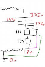
OK VERY rough sketch attached, purely to illustrate what I (probably wrongly) have in my head.
So R1 is "the normal cathode resistor", setting the bias. R2 lifts the starting point for R1.
Drawn this way purely to illustrate the question about where the bypass cathode should be grounded. I see 3 options, drawn in different colours;
- junction of R1/R2 - bypassing only the "normal cathode bias resistor"
- bottom of R2 - bypassing both resistors
- to 0v - also bypassing the choke coil in the ground return
Attachments
What's the choke for? It doesn't look a good driver stage to me....
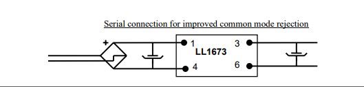
I plan to use Lundahl chokes in CMR mode. In this mode, 1 of the coils is connected in the ground return.
Attached is clipped from the 1673 datasheet
Attachments
- Status
- This old topic is closed. If you want to reopen this topic, contact a moderator using the "Report Post" button.
- Home
- Amplifiers
- Tubes / Valves
- All DHT Circuit Advice