William,
First, when I talked about voltage I meant RMS on a true RMS DMM.
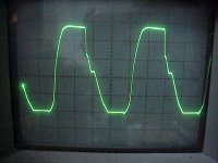
With 30V rails, 10kHz, I attain +/-40Vpp before clipping occurs. Bias is cranked up to 6.2A. When I make the amp clip, with or without load, I get the picture below. Note that I can't measure differential so this is only one half of the amp. DMM now reads 40V RMS. Indeed, this looks nasty but who would listen to this sound level without building a more powerful amp?")
As for the dip in the PSU, wouldn't that show the rather poor PSRR of this type of amp?
/Hugo
First, when I talked about voltage I meant RMS on a true RMS DMM.
With 30V rails, 10kHz, I attain +/-40Vpp before clipping occurs. Bias is cranked up to 6.2A. When I make the amp clip, with or without load, I get the picture below. Note that I can't measure differential so this is only one half of the amp. DMM now reads 40V RMS. Indeed, this looks nasty but who would listen to this sound level without building a more powerful amp?
As for the dip in the PSU, wouldn't that show the rather poor PSRR of this type of amp?
/Hugo
Attachments
Patrick,EUVL said:I think Hugo is measuring one output relative to ground ?
Patrick
I just spotted your post. Indeed, output to ground, as explained a few posts further.
/Hugo
I updated my thread with some more measurings.
See http://www.diyaudio.com/forums/showthread.php?s=&postid=1198207#post1198207
Xavier
See http://www.diyaudio.com/forums/showthread.php?s=&postid=1198207#post1198207
Xavier
Hi,
did a few more measurements this morning.
1. Tried Patricks sollution with an extra 5k plus 47uF to make sure only dc gets to the input diffs sources. This made no difference except for some oscillation.
2. removed the McMillans. No difference except for a somewhat difficult dc behaviour.
3. Played a bit with my variac to set different voltages and different absolute dc offsets. Here the influence was clear. The higher the supply voltage, the higher the voltage where the distortion starts.
For 10kHz into 8R I got the following results:
Vsupply 21,5 DC 3.5 Vdist. 22.12
Vsupply 21,5 DC 1.4 Vdist. 23.5
Vsupply 21,5 DC 0.4 Vdist. 24.4
Vsupply 20.0 DC -0:1 Vdist. 23.4
Vsupply 22.2 DC -5.0 Vdist. 24.92
Vsupply 22.2 DC 0.1 Vdist, 25.5
With the last two measurements there was also slight clipping at the top of the sinus.
So after having tried most things I´m back to the theory that it has something to do with the current sources. I will try to put these values in an excel sheet and play a bit with the various voltages. MAybe I´ll find something.
Since it is really a theoretical problem (my speakers have an impedance of 3 Ohms at 10kHz) I will leave it as it is at the moment cause my amps are sounding really wonderfull with the new front end and the newly trimmed C9 and 10.
If anybody else hase some other ideas please feel free to post......
William
Hi William,
I would think that the caps on the BJTs cause the distortion.
I know that you need them to stop oscillation. However, placing a 1000-2000pF caps across the output and before the gate-resistor of the gain MOSFET can usually stop the oscillation without caps on the BJTs. (The effect of this cap on the slew rate is less than that of increasing the negative feedback cap.)
Please try this as the last resource if it is not too much trouble.
wuffwaff said:
could you explain why you think those 460pF caps would cause little dips at 22V output voltage?
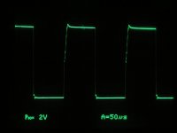
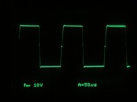
The attached photo (10KHz, 8V pp) was taken from my Aleph5 some time ago when a 4700 pF was put across C-E of the BJT. I think it has bad effect.
And where do you want the other caps placed? Between output and lower IRFP240? So 6 per amp.
No, just 1 per group of lower IRFP240 between Output and in front of the gate resistors.
Attachments
Hi,
I´m using 470pF over the bjt and the square wave looks quite a bit better than the one in your mail. What´s the nasty thing in the upward sweep? That sort of looks like my dip.......
I´ve tried everything from 100pF up to 4700pF and the 470pF gave the best results regarding oscillations and square wave performance.
Next time I open up the amp I´ll try your suggestion.
William
Today, I decided to swap toroids in the AlephX from 1000VA 22/22 to 625VA 15/15 because I wanted more bias. Since the capacity of the heat sinks are limited I had to lower the voltage.
Interestingly, I set the bias solely with the scope. I let the amp warm up for almost an hour, trimmed the offset very nicely to +/-10mV and then connected an 8ohm load to the output and a 1kHz sine wave to the input.
I raised the input voltage to the point where I could see a clipped sine wave on the scope and I swear it did look ugly.
Each halve of the amp got a probe attached and I set the scope in ADD mode. (Sum of both channels)
Then, I started trimming the two bias pots to make the wave form clip symmetrically.
I found that there seems to be some kind of sweet spot where a certain bias level is optimal; too little or too much bias results in earlier clipping. I would call it some kind of turnover point and carefully trimming both halves of the amp gives the highest unclipped wave form possible.
It always appeared to me that the bias limit was equal to the heat sink capacity. I can’t explain why but I found out this seems not to be the case.
After settings were done I checked with the DMM and the bias for both halves was perfectly equal for each halve of the amp.
At some point the scope picture looked quite similar to the one I saw from William.
I should check again if the bias was lower or higher from the sweet spot, don’t remember.
So William, from this experiment I conclude that playing with the bias setting might help solve your problem.
Let us know what you found if you find the time.
/Hugo
They are IRFP240.
There is most likely a simple explanation for what I found and I doubt I'd be the only one having noticed this behavior. Other than hooking up the scope and turning the pots, I wouldn't know how to establish a rule of thumb. It is perfectly possible that every amp will be different in respect to a certain voltage/current ratio.
/Hugo
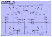
AlephX with J fet driver
Hi
I have these AlephX using the Kristijan PC boards .
Can I drive the AX with J fet .If yes can someone hepl me what do I have to change in the schematic so it make it better .
I attache the original schematic what these desing uses .
I have J fet 2SJ74BL/2SK170BL at least 50 pairs .Or if better to use 2SJ109BL/2SK264BL I can purchase that .
Can some one please help me please if is possibile to replace the Hexfet drivers wit J fet .
Thank for any help !!
Greetings
Attachments
- Status
- This old topic is closed. If you want to reopen this topic, contact a moderator using the "Report Post" button.
- Home
- Amplifiers
- Pass Labs
- AlephJ-X