Pass DIY Addict
Joined 2000
Paid Member
Very good summary of the project.
You must have lots of time.
Ha! I started building that web site back in 2003 when I began populating my circuit boards... I kept updating it over the years as various threads here grew and developed. Yes, little bits of time spread out across nearly 7 years!
 Like many things I life- I arrive a little late. The real activity on this amp was a few years ago...
And yes, the goldfish was helpful, too!

Eric
Pass DIY Addict
Joined 2000
Paid Member
Hi Eric,
for me your web site was very helpful.
I have just soldered my Aleph X and now waiting for transformer etc. to build up the amp.
For all decisions (which power, which parts ...) your web site was really important!
Thanks,
Marcel
Glad to hear it, Marcel! This is why I built my web page. When I first started my own amp, much of the the original Aleph-X Wiki was over my head so I wanted to create a more complete reference that would be easier for the novice like me to follow.
Just a note for those that have been following this thread, I have been regularly updating my Aleph-X web page as I have been constructing and testing my amplifier. All of the recent conversations here have been distilled down and captured at a level that should be accessible to almost anyone. In total, it is a document that spans nearly 40 pages if printed.
The URL is: Aleph-X 100w Amplifier Construction Notes
Again, my sincere thanks to all who have contributed and helped with this project! Special thanks to Magura and William who have provided excellent guidance during the final stages of bringing it all together!
Thank you!
Eric
Dear Eric,
congrats, thanks & rounds of applause (beside Mr. Pass & others) also to you...

Cheers,
Hi Eric,
Very nice build and a very nice website as well! Ik had a look at the site and mainly the construction photo's. I've got a question because of the hum you mention. Have you tried to isolate the center transformer clamping bolt and plate from the chassis? That has helped me in a few instances. I used an isolation ring from a cinch socket for that. Don't know why but it did.
regards,
Joris
Pass DIY Addict
Joined 2000
Paid Member
Hi Joris,
Thanks for your note. I did use a bicycle tire tube that I cut up to isolate the transformer from both the bottom of the chassis and the plate that sits on top of the transformer. When I first powered up the amp (and the bias was turned way down, the transformer was pretty quiet. It was only when I adjusted the bias up that it began buzzing. DC blockers help, but don't eliminate the problem completely.
I have a 1500VA on order that I'm expecting to show up within a week or so - maybe that will solve the problem.
Eric
Hi Eric,
I´m just back from a (very cold) bicycle holiday and saw the square waves. They look good but there seems to be a bit too much capacitance in the feedback path. What value did you use? 5pF or 10pF?
This would also explain the -3dB point at 80kHz which normally should be over 100kHz. You could try a bit less or leave it out.
Oh and thanks for the thanks!
William
Pass DIY Addict
Joined 2000
Paid Member
Pass DIY Addict
Joined 2000
Paid Member
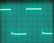
I removed the 10pF caps and re-measured the square waves and bandwidth with no cap at all. Bandwidth jumped from 80kHz to 240kHz. Sine waves still looked good all of way out to about 270kHz (at 10v p-p) at which point the traces on the scope began to blur. Clipping behavior, though, was a disaster. With the 10pF cap in place, clipping seemed "well behaved" with the extremes of the waves just flattening out as clipping set in. With no cap, all sorts of squiggles and strange, nasty, and non-symmetric distortions showed up.
Square waves certainly look more square, but now they have blips in them:
1kHz into 4 ohms at 10v p-p:

5kHz into 4 ohms at 10v p-p:
10kHz into 4 ohms at 10v p-p

20kHz into 4 ohms at 10v p-p

I just ordered a set of 1pH, 3pF, and 5pF caps, so I'll see which ones work best when they arrive.
Square waves certainly look more square, but now they have blips in them:
1kHz into 4 ohms at 10v p-p:
5kHz into 4 ohms at 10v p-p:
10kHz into 4 ohms at 10v p-p
20kHz into 4 ohms at 10v p-p
I just ordered a set of 1pH, 3pF, and 5pF caps, so I'll see which ones work best when they arrive.
Attachments
Last edited:
Pass DIY Addict
Joined 2000
Paid Member
William, Here are some pictures of the clipping behavior without the feedback caps in place.
1kHz clipping - no cap:

5kHz clipping - no cap:

10kHz clipping - no cap:

With the 10pF caps in place, clipping was a very neat and orderly event. The tops and bottoms of the sinewaves just flattened.
flg: Ha - I always feel like a chump when I realize I have paid for something I could have done myself... I twisted a few wires together and was quickly able to make something that measured 5pF, the trouble is that its value kept changing. Whatever I did, it wasn't stable over time. Thus, my feeling of being a chump quickly faded and I'm more than happy to wait for my ordered parts to arrive
1kHz clipping - no cap:
5kHz clipping - no cap:
10kHz clipping - no cap:
With the 10pF caps in place, clipping was a very neat and orderly event. The tops and bottoms of the sinewaves just flattened.
flg: Ha - I always feel like a chump when I realize I have paid for something I could have done myself... I twisted a few wires together and was quickly able to make something that measured 5pF, the trouble is that its value kept changing. Whatever I did, it wasn't stable over time. Thus, my feeling of being a chump quickly faded and I'm more than happy to wait for my ordered parts to arrive
Yes with all the efforts to isolate sound and vibration from the equipment in your system this could also be an issue. It may be possible to rectify that situatuion with silicone goop???
Regarding flat tops to the clipped waveform, transistor circuits are famous for behaving like that. That would essentially be creating many odd harmonics. This would likely be considered a harsh sounding nasty event. More ideal would be something that rounded or compressed more gradually. It is said tubes do such things and they sound very good when used in amplifier stages.
Can't say much about the radical clipping waveform other than my stuff does that sometimes too Even below clipping but that is probably for different reasons. At the very high end usually. You want to be compensating or rolling off before you get into that stuff.

Regarding flat tops to the clipped waveform, transistor circuits are famous for behaving like that. That would essentially be creating many odd harmonics. This would likely be considered a harsh sounding nasty event. More ideal would be something that rounded or compressed more gradually. It is said tubes do such things and they sound very good when used in amplifier stages.
Can't say much about the radical clipping waveform other than my stuff does that sometimes too
Even below clipping but that is probably for different reasons. At the very high end usually. You want to be compensating or rolling off before you get into that stuff.William, Here are some pictures of the clipping behavior without the feedback caps in place.
You will be interested to compare the differential output with
the absolute.
Pass DIY Addict
Joined 2000
Paid Member
Comparing Caps in the Feedback Loop
My new assortment of caps arrived yesterday and I spent some time comparing behavior of the amp with 1pF, 3pf, and 5pF caps in the feedback loop and made some composite images of the resulting square waves.
First up, I compared bandwidth:
0pF bandwidth = 240kHz (posted earlier)
1pF bandwidth = 210kHz
3pF bandwidth = 140kHz
5pF bandwidth = 120kHz
10pF bandwidth = 80kHz (posted earlier)
The next comparison shows square waves for 1pF, 3pF, and 5pF at 10v peak-to-peak output level across a range of frequencies:

The square waves below show various RMS levels of output at 1kHz for these three caps:

The square waves below show various RMS levels of output at 10kHz for these three caps:

The 1pF cap provides the widest bandwidth, but at the cost of ringing from 5kHz and higher frequencies, so I'm thinking this is not enough capacitance. The 3pF cap provides better corners than the 5pF cap, but at the 5v, 10v, and 15v RMS output level it also exhibits some ringing. The 5pF caps shows squares that are little more rounded than the 3pF caps, but the 5pF caps seem to show better control of ringing behavior.
If I changed the function generator to produce sine waves instead of square waves, all of the above measurement points look clean and undistorted.
In my unenlightened view, the 5pF caps looks like the best option with the least ringing and bandwidth to 120kHz. Any other opinions of these curves?
Nelson: I'll explore the differential vs absolute output in greater detail next - thanks for the suggestion!
My new assortment of caps arrived yesterday and I spent some time comparing behavior of the amp with 1pF, 3pf, and 5pF caps in the feedback loop and made some composite images of the resulting square waves.
First up, I compared bandwidth:
0pF bandwidth = 240kHz (posted earlier)
1pF bandwidth = 210kHz
3pF bandwidth = 140kHz
5pF bandwidth = 120kHz
10pF bandwidth = 80kHz (posted earlier)
The next comparison shows square waves for 1pF, 3pF, and 5pF at 10v peak-to-peak output level across a range of frequencies:
The square waves below show various RMS levels of output at 1kHz for these three caps:
The square waves below show various RMS levels of output at 10kHz for these three caps:
The 1pF cap provides the widest bandwidth, but at the cost of ringing from 5kHz and higher frequencies, so I'm thinking this is not enough capacitance. The 3pF cap provides better corners than the 5pF cap, but at the 5v, 10v, and 15v RMS output level it also exhibits some ringing. The 5pF caps shows squares that are little more rounded than the 3pF caps, but the 5pF caps seem to show better control of ringing behavior.
If I changed the function generator to produce sine waves instead of square waves, all of the above measurement points look clean and undistorted.
In my unenlightened view, the 5pF caps looks like the best option with the least ringing and bandwidth to 120kHz. Any other opinions of these curves?
Nelson: I'll explore the differential vs absolute output in greater detail next - thanks for the suggestion!
Last edited:
Pass DIY Addict
Joined 2000
Paid Member
William, I noticed the non-symmetric clipping, too. It seems most obvious in the 20v RMS traces in the last set of 10kHz waves. I'm not sure what is causing it. I'm wondering if the amp was not fully warmed up before I made these measurements. I did not check absolute DC offset before I began. I will double check this and see if the pattern persists.
If this is still present when the amp is fully warmed up, I am not sure what to check as I worked hard to make sure that both sides of the amp were well matched right down to each resistor...
This seems like a great time to follow up on Nelson's suggestion to check absolute vs. relative output. This will at least narrow things down to one side of the amp for me.
Eric
Pass DIY Addict
Joined 2000
Paid Member
I made more measurements last night looking for the source of the non-symmetric clipping behavior. I think I found it: I was using the wrong setting on my scope - Ch2 had been inverted (told you I was a noob... ) After correcting the scope setting (like before, the amp has been fine all along), I got a nice trace like this one for symmetric clipping behavior:

Nelson, you are a genius for coming up with super-symmetry! Also, thanks for your hint - it led me to realize I had the scope set incorrectly (but you already knew that...). I was really surprised when I compared the absolute output of each half of the amp with the differential output of both sides together! Each side by itself is not too pretty in the image below, but when you put 'em together, the result is quite nice! What a great design!

An finally, another composite image of square waves generated at 7.0vRMS (10v p-p) at 1kHz, 10kHz, and 20kHz comparing capacitance values in the feedback loop:

I think I like the square wave produced by the 3pF value the best. 5pF is too rounded and the 0pF and 1pF have bigger ripples...
Eric
) After correcting the scope setting (like before, the amp has been fine all along), I got a nice trace like this one for symmetric clipping behavior:
Nelson, you are a genius for coming up with super-symmetry!
Also, thanks for your hint - it led me to realize I had the scope set incorrectly (but you already knew that...). I was really surprised when I compared the absolute output of each half of the amp with the differential output of both sides together! Each side by itself is not too pretty in the image below, but when you put 'em together, the result is quite nice! What a great design!
An finally, another composite image of square waves generated at 7.0vRMS (10v p-p) at 1kHz, 10kHz, and 20kHz comparing capacitance values in the feedback loop:
I think I like the square wave produced by the 3pF value the best. 5pF is too rounded and the 0pF and 1pF have bigger ripples...
Eric
Last edited:
- Home
- Amplifiers
- Pass Labs
- Aleph-X builder's thread.