Pass DIY Addict
Joined 2000
Paid Member
Magura: Yes I have, but not on my normal speakers yet - I only have one channel working. I wanted to make sure that everything was good with one before I make 2 more of them. When the amps are done, I have a speaker project to build next. It is based on the Dayton RS28a tweeter, two HiVi Midwoof M8a, and two Dayton rss315hf-4 woofers. I have all of the drivers, but haven't yet gathered the crossover components.
ZenMod: Thanks for catching my error! I meant to indicate 2SJ74BL - I mistakenly copied the N-channel part number instead of the P-channel part number. Since Graeme's design used (4) pieces of 2SJ109BL, it looks like I will need (8) pieces of 2SJ74BL for each monoblock. I presume in this case that all eight will need to be closely matched to one another? Or is it sufficient to use 4 sets of matched pairs? I found another thread from Graeme (I think) where he made arrangements with someone to produce a tandem heat sink so they track thermally with one another.
I think I'm suffering from information overload. I need to re-read some of this again.
Last edited:
Hi Eric,
you can use XLR only when your function generator is balanced. Otherwise use RCA and connect -IN to ground via a coupling cap (the same as used in the +IN)
only two fets are needed wich should be closely matched. You can use a small pot (10R) as a pair of source resistors to make small adjustmants to the rel. dc offset.
First I would try to solve the problems you´ve got with the 9610´s in place. Listen for a year or two and then change to Jfet´s. This will have twice the fun ;-)
William
Last edited:
Pass DIY Addict
Joined 2000
Paid Member
Hi William,
Yes, I want to make sure that things are working properly with the 9610s before making any changes. One thing at a time.
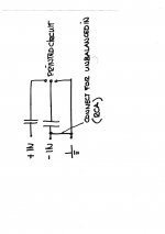
When I built my amp, I completely forgot about the coupling caps I have attached a drawing. Are the caps indicated correctly?

thanks!
Eric
Ooops: forgot to add that the RCA terminal is electrically isolated from the metal chassis. The Shield/Ground input on the PCB is connected directly to power supply ground (zero voltage point at the caps), which then goes to AC mains ground through a CL-60 thermistor.
Yes, I want to make sure that things are working properly with the 9610s before making any changes. One thing at a time.
When I built my amp, I completely forgot about the coupling caps
I have attached a drawing. Are the caps indicated correctly?
thanks!
Eric
Ooops: forgot to add that the RCA terminal is electrically isolated from the metal chassis. The Shield/Ground input on the PCB is connected directly to power supply ground (zero voltage point at the caps), which then goes to AC mains ground through a CL-60 thermistor.
Last edited:
Pass DIY Addict
Joined 2000
Paid Member
Yikes! Good thing I forgot about adding this in and its not in the circuit yet! This looks better to me and now I see how it actually blocks DC input from the processor.
Thanks for your patience with me, William! As with most of my projects, I get half way through them and think to myself "wow- this just got way more complicated than I originally thought it would be..." The good news is that I'm almost through with this one...
Good thing I forgot about adding this in and its not in the circuit yet! This looks better to me and now I see how it actually blocks DC input from the processor. Thanks for your patience with me, William! As with most of my projects, I get half way through them and think to myself "wow- this just got way more complicated than I originally thought it would be..." The good news is that I'm almost through with this one...
Pass DIY Addict
Joined 2000
Paid Member
I'm still waiting to borrow a scope for use at home to do some additional analysis of the wave forms, so in the mean time I played around with offset and bias after letting things warm up for an hour. The only thing that I didn't think to check was bias through the front-end differential. I let the amp warm up for a full hour. Absolute DC offset started at 9.0v upon powerup, was at 3.9v by 5 mins, was at 1.86v by 30mins, and at 0.5v at 60mins. At this point, I readjusted bias to 8.0A and reset Absolute Offset to as close to zero as I could (-0.08v). I was then able to measure AC Current Gain at 49.7% on one side and 49.4% on the other side.
Overall, I am using 4 sinks and have 3 mosfets mounted to each sink (designated by L, C, and R in the image). I'm a little surprised that the power dissipated by the mosfets don't more closely match one another, although they are very close. I'm not going to change any of these settings until I can hook it to a scope again to look at the output waveforms. Music sounds nice, but again, I only have one working channel so its difficult to judge.
Heat sink temperatures may not be very precise - all I had was my non-contact infrared gun and I searched the sink for the highest temperature I could find. This ended up being just above the center fet on each sink. I was surprised to find a near 50c rise... Moving to bigger sinks clearly looks like a good idea!
All of my measurements are in the graphic below:

Overall, it looks like the transformer, the two bridge rectifiers, and the PCB are burning about 40w.
The transformer still hums pretty good (which I presume is due to being overloaded). Just for kicks, I tried using a DC blocker, but it didn't make much difference. What I have is an electrolytic cap (don't remember its uF) with two anti-parallel diodes across it and this is in series with the transformer primary. Is there another configuration I should try?
Overall, I am using 4 sinks and have 3 mosfets mounted to each sink (designated by L, C, and R in the image). I'm a little surprised that the power dissipated by the mosfets don't more closely match one another, although they are very close. I'm not going to change any of these settings until I can hook it to a scope again to look at the output waveforms. Music sounds nice, but again, I only have one working channel so its difficult to judge.
Heat sink temperatures may not be very precise - all I had was my non-contact infrared gun and I searched the sink for the highest temperature I could find. This ended up being just above the center fet on each sink. I was surprised to find a near 50c rise... Moving to bigger sinks clearly looks like a good idea!
All of my measurements are in the graphic below:
Overall, it looks like the transformer, the two bridge rectifiers, and the PCB are burning about 40w.
The transformer still hums pretty good (which I presume is due to being overloaded). Just for kicks, I tried using a DC blocker, but it didn't make much difference. What I have is an electrolytic cap (don't remember its uF) with two anti-parallel diodes across it and this is in series with the transformer primary. Is there another configuration I should try?
Last edited:
Pass DIY Addict
Joined 2000
Paid Member
Hi William,
Thanks for your comments about my measurements - its reassuring to know that I've done a few things correctly I measured bias through the differential pair on the front end tonight and confirmed 11.8mA through each 9610.
I was playing around with my DC blocker and made a new discovery (I feel just like a kid with a new toy!). I have a Nichicon VX(M) series polarized electrolytic cap that is rated at 4700uF, 35v, 85c. Across the poles of the cap are two anti-parallel diodes that I think are rated at 5A or 6A (I don't remember which...). I think I picked up these parts at the local Radio Shack store a few years ago - they are pretty typical and common parts.
So, I tried a few things. When I put the cap in series with the hot leg from the AC socket so that the current flows in the direction indicated on the cap (wall socket -->cap--> amp), there is a very small (but noticeable) reduction in the transformer hum. With my DMM, I can measure about 0.006v DC across the cap. This reduction in hum is small enough that it is easy to miss (like last night - tonight I was working in a more quiet room). Now, if I keep the cap and diodes on the hot leg, but reverse the direction of the cap so that the current flows opposite of the direction indicated on the body of the cap (wall socket <--cap<-- amp), I get a much greater reduction in transformer hum and can measure 0.014v DC across the cap.
The behavior is exactly the opposite if I put the DC blocker on the neutral line from the AC socket. When I insert the cap and diodes so that the current flows in the direction indicated on the cap (wall socket -->cap--> amp), there is a clear reduction in the transformer hum. With my DMM, I can measure about 0.014v DC across the cap. Now, if I keep the cap and diodes on the neutral line from the AC socket, but reverse the direction of the cap so that the current flows in the opposite direction indicated on the body of the cap (wall socket <--cap<-- amp), I get a very small reduction in transformer hum again and can measure only 0.006v DC across the cap.
After a few minutes with the DC blocker installed, the diodes get a little warm, but clearly not hot. Inserting the DC blocker drops the rail voltage by about 0.2v. In all cases above, if I use my test clips to short the cap, the hum returns immediately (though it seems to oscillate a little with somewhat random timing). All of this testing was done with a cold amp and a few volts of Absolute DC Offset present.
So I have two questions:
1) Is there any reason not to install a DC blocker on BOTH the hot and neutral lines coming from the AC wall socket?
2) Is there any problem with installing the DC blocker so that the current flows in the opposite direction as indicated on the body of the cap (this provides the greatest reduction in transformer hum)? I'm just concerned that the cap might cause some problem with long-term "backward" use.
Thanks,
Eric
Thanks for your comments about my measurements - its reassuring to know that I've done a few things correctly
I measured bias through the differential pair on the front end tonight and confirmed 11.8mA through each 9610.I was playing around with my DC blocker and made a new discovery (I feel just like a kid with a new toy!). I have a Nichicon VX(M) series polarized electrolytic cap that is rated at 4700uF, 35v, 85c. Across the poles of the cap are two anti-parallel diodes that I think are rated at 5A or 6A (I don't remember which...). I think I picked up these parts at the local Radio Shack store a few years ago - they are pretty typical and common parts.
So, I tried a few things. When I put the cap in series with the hot leg from the AC socket so that the current flows in the direction indicated on the cap (wall socket -->cap--> amp), there is a very small (but noticeable) reduction in the transformer hum. With my DMM, I can measure about 0.006v DC across the cap. This reduction in hum is small enough that it is easy to miss (like last night - tonight I was working in a more quiet room). Now, if I keep the cap and diodes on the hot leg, but reverse the direction of the cap so that the current flows opposite of the direction indicated on the body of the cap (wall socket <--cap<-- amp), I get a much greater reduction in transformer hum and can measure 0.014v DC across the cap.
The behavior is exactly the opposite if I put the DC blocker on the neutral line from the AC socket. When I insert the cap and diodes so that the current flows in the direction indicated on the cap (wall socket -->cap--> amp), there is a clear reduction in the transformer hum. With my DMM, I can measure about 0.014v DC across the cap. Now, if I keep the cap and diodes on the neutral line from the AC socket, but reverse the direction of the cap so that the current flows in the opposite direction indicated on the body of the cap (wall socket <--cap<-- amp), I get a very small reduction in transformer hum again and can measure only 0.006v DC across the cap.
After a few minutes with the DC blocker installed, the diodes get a little warm, but clearly not hot. Inserting the DC blocker drops the rail voltage by about 0.2v. In all cases above, if I use my test clips to short the cap, the hum returns immediately (though it seems to oscillate a little with somewhat random timing). All of this testing was done with a cold amp and a few volts of Absolute DC Offset present.
So I have two questions:
1) Is there any reason not to install a DC blocker on BOTH the hot and neutral lines coming from the AC wall socket?
2) Is there any problem with installing the DC blocker so that the current flows in the opposite direction as indicated on the body of the cap (this provides the greatest reduction in transformer hum)? I'm just concerned that the cap might cause some problem with long-term "backward" use.
Thanks,
Eric
Last edited:
Hi Eric,
the current will flow in both directions because I suppose you´ve got AC coming out off (and going into again) the wall socket. Normally there shouldn´t be any difference wich way round you put the blocker nor in wich line you put it (live or neutral)
The diodes shouldn´t conduct any current at all when DC is below 0,7V. You should measure AC current across them, not DC. AC should be very small (<<0,7V) otherwise current will flow through the diodes. If this is the case you should choose a bigger cap.
William
Last edited:
Pass DIY Addict
Joined 2000
Paid Member
Hmmm... This seems curious. I'll pick up another cap and set of diodes tonight on the way home from work and see what happens if the DC blockers are installed on both the hot and neutral lines from the socket. I'll also measure AC voltage across the cap and see what I get. This might just solve the transformer hum problem for me...
Thanks!
Eric
Thanks!
Eric
Pass DIY Addict
Joined 2000
Paid Member
I did some additional testing and measurements last night. The DC Blocker does clearly reduce transformer hum, but does not entirely eliminate it. I tried anti-parallel diodes across the cap on just the hot lead, across just the neutral lead, and across both leads at the same time. I tried back to back (in series) caps with anti-parallel diodes across the series. These each reduced hum by a large amount (perhaps 75%-80% of the hum was gone), but nothing completely eliminated it. Perhaps the remaining hum is due to the heavy load on the transformer...
Then I measured the voltage across the cap and diode combination. Depending upon the direction of the cap with respect to the current flow, I could reliably measure either 0.006 or 0.014 vDC across the cap. When I switched the meter to AC mode, however, I was able to measure approximately 0.7 to 0.8 vAC across the hot leg and 0.8 to 0.9 vAC across the neutral leg. This surprised me a little given that you seem to feel that my AC voltages should be much lower...
For all of these test, I used a 4700uF 35v cap (Nichicon specifies ripple current rating of about 1A). I then tried a 15,000uF 16v electrolytic cap, with no change in AC voltage readings across the cap... Do I need to use an even larger cap (I have a few 35,000uF 35v computer grade caps laying around) or is this indicative of a different type of problem?
Thanks!
Eric
Pass DIY Addict
Joined 2000
Paid Member
Interesting suggestion, labjr. I do have a big 2000VA toriod that I use to drive the entire entertainment system in the family room. The primary is 120v and has a center tapped 60-0-60 secondary that I use for balanced power output. Its about 12" in diameter and weighs in at about 40-45 lbs all by itself.
Certainly, this should block any DC on the AC mains. I presume that any resulting transformer hum in the amp would be the result of things not related to DC voltage on its core (uneven windings, uneven loads, heavy load, etc).
Thanks for this suggestion! I've had that big balance power toroid for so long, I forgot that its there... Duh...
Last edited:
Pass DIY Addict
Joined 2000
Paid Member
Funny things, those transformers! When I plugged my Aleph-X into my 2000VA, the toriod in the amp still buzzes a bit (I guess at this point we are dealing with strange stuff in the windings or just too much load) but the funny part is that it made the big 2000VA hum as well! Perhaps it, too, is somewhat irregular and is why I was able to put my hands on it years ago.
Pass DIY Addict
Joined 2000
Paid Member
New Measurements
Its taken a while, but I was finally able to do another round of measurements. This time, I used both channels of a 2-channel scope with the scope set to sum. One channel was connected to Speaker Pos, the other channel was connected to Speaker Neg, and the ground leads from both channels were connected together at the PSU grounding point.
Bandwidth -3dB points (0dB point measured at 1kHz) occurred at 10Hz and close to 80kHz. Sine waves are beautiful and undistorted from about 7Hz up to over 200kHz (I didn't measure beyond this point). Here is a 10kHz wave:
Square waves are much cleaner than what I posted previously. These were measured into a 4ohm load at 10v RMS (14v p-p). The amp is running at about 8A bias point on 21v rails.
50Hz Square wave below:

100Hz Square wave below:

500Hz Square wave below:

1kHz Square wave below:

5khz Square wave below:

10kHz Square wave below:

15kHz Square wave below:

20kHz Square wave below:

Square waves were measured into a 4 ohm load at 10vRMS (about 14v peak-to-peak) output level. Although the square waves look a little funny below about 100Hz and then again above 10kHz, they look noticeably cleaner than those from my Marantz MA500 amps and the bandwidth is wider, too.
I also looked a clipping behavior, which was really very nice. The sine waves were very clean and when clipping set in they just flattened out on the top and bottom - no funny ripples or dips in the curves this time. I am much more pleased with this set of measurements. I think the major problem with my last set of curves that I posted was my measurement method - I just connected the + and - from a single probe across the output resistor which effectively grounded the output of half of the amp.
Is it critical that bandwidth extend higher than the 80kHz I have measured? If so, what can be done to extend it?
Does anything need to be done with the square wave performance (especially looking at 15kHz and 20kHz), or is this a good reference point?
Thanks!
Eric
Its taken a while, but I was finally able to do another round of measurements. This time, I used both channels of a 2-channel scope with the scope set to sum. One channel was connected to Speaker Pos, the other channel was connected to Speaker Neg, and the ground leads from both channels were connected together at the PSU grounding point.
Bandwidth -3dB points (0dB point measured at 1kHz) occurred at 10Hz and close to 80kHz. Sine waves are beautiful and undistorted from about 7Hz up to over 200kHz (I didn't measure beyond this point). Here is a 10kHz wave:
Square waves are much cleaner than what I posted previously. These were measured into a 4ohm load at 10v RMS (14v p-p). The amp is running at about 8A bias point on 21v rails.
50Hz Square wave below:
100Hz Square wave below:
500Hz Square wave below:
1kHz Square wave below:
5khz Square wave below:
10kHz Square wave below:
15kHz Square wave below:
20kHz Square wave below:
Square waves were measured into a 4 ohm load at 10vRMS (about 14v peak-to-peak) output level. Although the square waves look a little funny below about 100Hz and then again above 10kHz, they look noticeably cleaner than those from my Marantz MA500 amps and the bandwidth is wider, too.
I also looked a clipping behavior, which was really very nice. The sine waves were very clean and when clipping set in they just flattened out on the top and bottom - no funny ripples or dips in the curves this time. I am much more pleased with this set of measurements. I think the major problem with my last set of curves that I posted was my measurement method - I just connected the + and - from a single probe across the output resistor which effectively grounded the output of half of the amp.
Is it critical that bandwidth extend higher than the 80kHz I have measured? If so, what can be done to extend it?
Does anything need to be done with the square wave performance (especially looking at 15kHz and 20kHz), or is this a good reference point?
Thanks!
Eric
Last edited:
Pass DIY Addict
Joined 2000
Paid Member
Thanks, Magura! Now that it works (it was just really a matter of measuring properly to verify that it was working) its time to tear it apart for a bigger transformer and more heat sinking. Then I need to build 2 more! Then its time to shift gears to the speaker project...
Thank you for your help!
Eric
Thank you for your help!
Eric
Pass DIY Addict
Joined 2000
Paid Member
Just a note for those that have been following this thread, I have been regularly updating my Aleph-X web page as I have been constructing and testing my amplifier. All of the recent conversations here have been distilled down and captured at a level that should be accessible to almost anyone. In total, it is a document that spans nearly 40 pages if printed.
The URL is: Aleph-X 100w Amplifier Construction Notes
Again, my sincere thanks to all who have contributed and helped with this project! Special thanks to Magura and William who have provided excellent guidance during the final stages of bringing it all together!
Thank you!
Eric
The URL is: Aleph-X 100w Amplifier Construction Notes
Again, my sincere thanks to all who have contributed and helped with this project! Special thanks to Magura and William who have provided excellent guidance during the final stages of bringing it all together!
Thank you!
Eric
Last edited:
Again, my sincere thanks to all who have contributed and helped with this project! Special thanks to Magura and William who have provided excellent guidance during the final stages of bringing it all together!
Thank you!
Eric
It's almost like winning an Oscar
"I would like to thank my mum and dad, and the unbelievable support from my goldfish"
Magura
- Home
- Amplifiers
- Pass Labs
- Aleph-X builder's thread.