
You can find it in the Wiki http://www.diyaudio.com/wiki/index.php?page=Aleph-X
and here is a direct link:
http://www.diyaudio.com/forums/showthread.php?s=&threadid=27170
and here is a direct link:
http://www.diyaudio.com/forums/showthread.php?s=&threadid=27170
Do the output FET's need to be thermal matched?
HI,
I was considering an AlephX design of one FET per heatsink. I know most people are grouping each side of a mono channel to one heatsink each.
I'm looking at using 12 smaller heatsinks, one per output FET. After running the numbers on the AlephX spreadsheet each FET would dissipate 20 watts each for a single channel 100 watt amp. The heatsink thermal resistance is .08 per FET using 12 sinks.
From what I was able to read this seems OK, but let me know if I'm making a mistake.
Thanks!
-David
I think you are making a mistake
0.08 K/W seems a little too good for a single heatsink for one single FET dissipating only 20 Watts.........")
At 0.08 K/W you could easily dissipate 100 ++ Watts per sink and it would be rather big in size.
Is this value correct?
Check this value for your heatsink or post its dimensions or a picture of it if you already have the sink.
It would be easy for people here to give an estimate of it's K/W value.
0.08 K/W seems a little too good for a single heatsink for one single FET dissipating only 20 Watts.........
At 0.08 K/W you could easily dissipate 100 ++ Watts per sink and it would be rather big in size.
Is this value correct?
Check this value for your heatsink or post its dimensions or a picture of it if you already have the sink.
It would be easy for people here to give an estimate of it's K/W value.
Thanks Byteboy,
Here's a link to the heatsink: http://www.aavidthermalloy.com/bin/...45&airflow=57.2&ExLength=4.000&LengthUnits=in
At four inches the heatsink has thermal resistance value of .97. I should have been more clear, the .08 value was .97/12=.08 as per cell B64 for the Rth value in the AlephX spreadsheet.
Thank you,
-David
Thats cool!!
OK David, I think you are OK with that value, I got you wrong there!
At a total K/W of 0.08 for 12 heatsinks of 0.97 K/W each, you should be pretty much on the safe side!
For 100 Watts @ 8 Ohm, @ 0.08 K/W total @ abt. 21°C/70°F ambient temperature, you will have abt. 40°C/100°F heatsink temperature.
Thats cool!!
With 12 of such heatsinks it will be a BIG amp though....
But that's cool too!!!!!
Yea, it will be fairly large. I estimate each amp will be 22Wx18Dx8H in inches or for our metric friends.. 559Wx457Dx203H in mm going with this approach. I really struggled with the fact that these amps run hot and opted to perhaps over heatsink them.
Does anyone know if there is a downside to not having the output FETs thermally coupled?
Thanks!
-David
Does anyone know if there is a downside to not having the output FETs thermally coupled?
Thanks!
-David
Fet choice
Hi i am a newby in this forum and the thread is very long so here a few questions.
Are the PCB's still available anywhere?
I have a lot of Fairchild 75345p laying around (bought 150 of them for 15$) can i use them instead of the irfp044.
Specs are about the same only slightly lower voltage (55 instead of 60) but higher current (75A) and much dissipation.
I also have some irfp450's laying around but not so much so matching would be more difficult.Which would be the better option?
Re: Fet choice
Maybe I was mistaken.
I live less then 15 minutes away from you, if you are going to build the amp, maybe we can order parts together to get some discount.
Also check this page:
http://www.diyaudio.com/wiki/index.php?page=Aleph-X
Yesterday I saw a PCB group buy, now I can't find it anymore.kro5998 said:Hi i am a newby in this forum and the thread is very long so here a few questions.
Are the PCB's still available anywhere?
Maybe I was mistaken.I live less then 15 minutes away from you, if you are going to build the amp, maybe we can order parts together to get some discount.
Also check this page:
http://www.diyaudio.com/wiki/index.php?page=Aleph-X
I'm very sorry, but I can't edit the post above. Here is the groupbuy:
http://www.diyaudio.com/wiki/index.php?page=AX
http://www.diyaudio.com/wiki/index.php?page=AX
I have a small question.. do you guys know anyone who built Aleph X with a E-I core tranny? how did it sound?
i asked because im really interested in this amp and i think i can manage, but times are bad lately in this part of our little planet. hehe just the monetary conversion alone to get torroids is killing me.
Any replys is highly appreciated and would help a lot in my rough planning.thanks and sorry if i disturb the flow of the discussion.
E/I core transformer
fish4u
I don't think there should be big sonic differences between a toroid and an E-I transformer.
If you can deal with the larger size and weight for a given power rating (probably meaning a bigger/stronger chassis) and you take care of the bigger stray EM-field of an E/I core type transformer, there shouldn't be a problem; I even read somewhere on the forum that due to the smaller "bandwidth" of an E/I type transformer you would have less trouble with powerline noise/-interference if present.
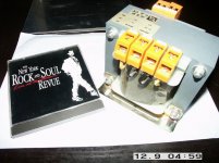
I myself am building a kind of stereo 50~100W "prototype'' AlephX with two 12/18/24V-320VA E/I type transformers and from parts I already had laying around or could get dirt cheap to get some experience with the AlephX .
It will be some time though, before I can give you some sound quality impressions, things go slow with this project.......
fish4u
I don't think there should be big sonic differences between a toroid and an E-I transformer.
If you can deal with the larger size and weight for a given power rating (probably meaning a bigger/stronger chassis) and you take care of the bigger stray EM-field of an E/I core type transformer, there shouldn't be a problem; I even read somewhere on the forum that due to the smaller "bandwidth" of an E/I type transformer you would have less trouble with powerline noise/-interference if present.
I myself am building a kind of stereo 50~100W "prototype'' AlephX with two 12/18/24V-320VA E/I type transformers and from parts I already had laying around or could get dirt cheap to get some experience with the AlephX .
It will be some time though, before I can give you some sound quality impressions, things go slow with this project.......
Attachments
also, you'll need two decks on the switch per band/ (4 decks per channel on a two way) since you need a constant impedance attenuator to keep your passive XO working as expected. that's one of the reasons I went active. May I suggest that the filter drive a buffer stage with a decent pot following to trim the level of the band?
Oh - now I see what you want to do - R16/R19 and R27/R29 determine the gain, 10 (20dB) in Gray's AX10 schematic. just be sure that R16=R27 and R19=R29.
Changing the gain may change the sound character of the AX. You could use a fixed attenuator on the higher level filter. just two more high quality resistors, although you may find that you need funky values to keep the load on the filter constant.
Changing the gain may change the sound character of the AX. You could use a fixed attenuator on the higher level filter. just two more high quality resistors, although you may find that you need funky values to keep the load on the filter constant.
Thanks.
Can you please elaborate?Changing the gain may change the sound character of the AX.
You mean the highpass? I plan to send the lowpass to an Aleph-X and the highpass to a different amplifier, so I'm only asking about the lowpass. The crossover I'm looking at is this one.You could use a fixed attenuator on the higher level filter.
I don't know for sure if it will change the character of the sound, but you would change the gain by changing the amount of feedback (more gain=less feedback) so it might have a noticeable effect.
OK - I somehow read you were using a passive XO. With that XO, just use a fixed attenuator on whichever subsystem (amp/driver) is too loud. Need more highs? attenuate the lows. need more lows? attenuate the highs. You could use a pot to find how much attenuation is needed then measure the setting and make a fixed resistive divider accordigly.
As Byteboy suggested, your best performance would be with your volume control after the XO. Add another stepped attenuator driven off the same motor or controller? you could make the new one attenuate more than the other at the same position to match high and low levels. Or just go with the attenuator upstream of the XO and live with the extra noise.
- Home
- Amplifiers
- Pass Labs
- Aleph-X builder's thread.