Pass DIY Addict
Joined 2000
Paid Member
Hi Judmarc,
Welcome to DIYAudio! There are a LOT of great people around that can help provide some guidance for you as your projects unfold. I've been hanging around here for 10 years and have learned a great deal, but there are many others that know a great deal more than I do.
While I haven't searched for the specific model you listed, my presumtion is that its an international version of the Aleph30 design. Schematics and build discussions abound. Yes, the Aleph-X as described on this forum is a very close match to the Pass Labs XA series of amps. I think Nelson indicated some time ago that it was probably a 95% match in topology. Have a look at the link in my signature for a lengthy A-Z read on building one of these amps. My advice would be not to limit yourself to trying to shoe-horn a new amp into an old chassis. Power output requirements will determine the size of the heatsinks you need, and thus will determine your final chassis size, so source those first.
Welcome!
Eric
its an
Not really.
The INT-30/XA30.5 power amp is a combined single-ended & push-pull design (sorta next step up from the Aleph 0/0s originals).
UGS front end with SuSY, and four quadrants of 5 output devices.
Single-Ended operation is achieved by 'simply' putting a handfull of power resistors in parallel across the other phase of each side.
See images of INT-30 innards : 20 output devices per channel, with 32 of the familiar Panasonic R's.
(eeh, cough, some of them are such a high Kb size that you can read the Ohmic value of the S-E load resistors )
Last edited:
Thanks, Eric, I appreciate the warm welcome. The Int-30A is an integrated amp, a preamp plus the XA30.5 in one chassis.
The dimensions I gave were actually for the bay in the piece of furniture where I house my audio equipment. From what you've indicated, in order to see whether I can fit a stereo amp chassis in that bay, I need to work backwards from dimensions to heatsink size to the power output whose heat dissipation requirements match that heatsink size. What's a good reference for me to examine heatsink size requirements for various power outputs?
Thanks again to Eric and all the other folks in this forum.
The dimensions I gave were actually for the bay in the piece of furniture where I house my audio equipment.
Thanks again to Eric and all the other folks in this forum.
Pass DIY Addict
Joined 2000
Paid Member
Pass DIY Addict
Joined 2000
Paid Member
Judmarc, here is a quick tutorial to get you going. Go to the "which version/parts list" section of my web page and click the link for William's AXE1-2 spreadsheet. This is a great estimator for a number of aspects of any proposed design. The spreadsheet is already filled in with values that will result in an amp that can deliver about 100w into either an 8ohm or 4ohm load.
Start with cells B12 and B13 - these determine your power supply. Play around with these first and note the changes in power output indicated in cells B17 and B18. There are interesting relationships between Voltage and Bias Current to note. B15 is where you specify the number of output devices for your amp. This needs to be a multiple of 4 (by design) and use the value in B23 as a guide for changing B15. If B23 goes much below 20, decrease B15 by 4. If B23 goes much above 30, increase B15 by 4.
Play with these cells until you arrive at a power specification that suits your needs. Then have a look at B66. This is where you specify the total heat sink capacity (per mono) for your amp. Then have a look at B80 and B82. You want to increase your heat sink capacity (decrease the value in B66) until B80 is kept under 100c and B88 is kept under 50c or so. Play around for a while until you get a feel for the relationships...
Then you can start shopping for heat sinks. There is a dealer here on DIYAudio as well as a number of other places. Its far less expensive to purchase surplus/used, but its also harder to find what you need.
It looks daunting, but do read through my Aleph-X page.
Eric, thanks once again. Been going through some distractions since I last posted, such as weather causing prolonged power outage (I'm in Eastern PA).
I'm very definitely a newbie and it took a bit of adjusting to come to grips with terms. I think I've got it, but will list my assumptions anyway, just to confirm I haven't done this exactly wrong:
- Dimensions on heatsink drawings correspond to those mounted on an amp (fins running vertically) as follows - height on drawing (e.g. 2.2" for MM11645) is depth, or how far the heatsink projects forward, as mounted; width on drawing (6.695" for MM11645) is width as mounted; and length (not indicated on MM11645 drawing except as spec of 0.8c/w for 3" length) is height of fins/heatsink from top to bottom as mounted.
- When you indicate you "add together" the dissipation numbers for heatsinks to get the total, this actually results in *reducing* the c/w, since the heatsinks will now have a lower temperature rise per watt.
As I mentioned before, I've got my equipment in an open-front cabinet with bays of the following dimensions: 8" high, 23" deep, 22" wide. The back is closed except for a horizontal 2" high slot across the lower back of each bay for signal and power connections. This means in order to get decent cooling for a stereo amp in the cabinet, my heat sinking will need to be on the front of the amp and project from the front of the cabinet, where it can get out from under the top of the bay. Leaving 1" of room at top, bottom, and sides of the amp so it can fit in the bay gives heatsink height and width dimensions (as mounted - on a drawing they'd be the length and width dimensions) of ~6" x 20".
My understanding from reviewing the info at your site is that doubling the length (height as mounted) of the MM11645 sink from 3" to 6" increases its ability to dissipate by the square root of 2. Dividing 0.8 by 1.41 gives me about .57c/w. Then placing 3 such sinks across the front of the amp would give .57 divided by 3, or .19c/w as the dissipation capacity I should aim for. With this as my design limitation, I find from William's AXE1-2 spreadsheet that a stereo amp of ~50wpc is probably the reasonable limit as far as power. (B12=16, B13=5, B15=8, B17=49, B18=50, B23=20, B66=0.19, B80=69.8, B82=50.4)
My present amp is a PSE Studio IV rated at 100wpc, running a pair of Vandersteen 2Ce speakers spec'd at 7 ohms nominal, 4 ohms minimum. Efficiency spec is quoted as 86dB with 2.83 volts of pink noise input at 1 meter on axis. I very, very seldom turn the preamp (Spectral DMC-12) volume control up as far as ~ the 11 o'clock position with this setup. In usual listening (alone, without my wife asking me to turn it down), volume control is around the 10 o'clock position.
So here's a question for anyone who may own or has heard an Aleph-X (or at any rate, a Pass Class A amp design, especially a DIY version) in the 40 or 50 wpc range with the Vandersteen 2 or similarly spec'd speakers: Will a 50wpc Aleph-X be sufficient to comfortably run my speakers, especially during those odd times when I want to "turn it up"?
high power aleph-x
Hello follow diyers.
Just wondering if someone have boards to sell?? I bought the aleph-x from jims audio and now that I'm aware the copyright issues I'm a little embarresed, but the board are almost done with expensive parts.....

anyone know if the parts will fit the original boards?
ps. did donate to make my mind at ease .
.
thanks.
soon to start the BA3 project
schema:
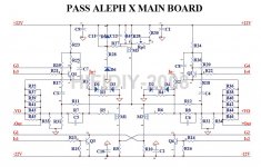
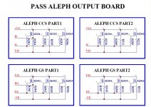
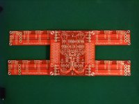
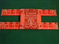
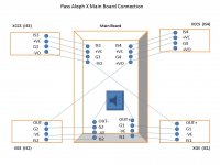
Hello follow diyers.
Just wondering if someone have boards to sell?? I bought the aleph-x from jims audio and now that I'm aware the copyright issues I'm a little embarresed, but the board are almost done with expensive parts.....
anyone know if the parts will fit the original boards?
ps. did donate to make my mind at ease
thanks.
soon to start the BA3 project
schema:


Pass DIY Addict
Joined 2000
Paid Member
Eric, thanks once again. Been going through some distractions since I last posted, such as weather causing prolonged power outage (I'm in Eastern PA).
Sorry to hear about the power loss. My sister in NJ was also without power for a few days. I keep contemplating a generator but haven't gotten one yet...
- Dimensions on heatsink drawings correspond to those mounted on an amp (fins running vertically) as follows - height on drawing (e.g. 2.2" for MM11645) is depth, or how far the heatsink projects forward, as mounted; width on drawing (6.695" for MM11645) is width as mounted; and length (not indicated on MM11645 drawing except as spec of 0.8c/w for 3" length) is height of fins/heatsink from top to bottom as mounted.
In the technical drawing, you are looking at a cross section. Width is as specified (6.69"), length is your custom cut (mine are 10" long) and height is the measurement from the end of the fin back to the back plate (thick part on bottom of technical drawing). Mounted on my amp, the fins run up and down, perpendicular to the floor. This facilitates the best airflow for optimum cooling without a fan.
- When you indicate you "add together" the dissipation numbers for heatsinks to get the total, this actually results in *reducing* the c/w, since the heatsinks will now have a lower temperature rise per watt.
Yes, it's a bit counter intuitive. Say the c/w rating for whatever length = 0.20c/w. If you have two of them side by side (not one "on top of" the other), their total is now 0.10c/w. Lower numbers indicate greater cooling capability. If you have three of them side by side, your c/w rating is now 0.20c/w divided by 3 or about 0.07c/w.
As I mentioned before, I've got my equipment in an open-front cabinet with bays of the following dimensions: 8" high, 23" deep, 22" wide. The back is closed except for a horizontal 2" high slot across the lower back of each bay for signal and power connections. This means in order to get decent cooling for a stereo amp in the cabinet, my heat sinking will need to be on the front of the amp and project from the front of the cabinet, where it can get out from under the top of the bay. Leaving 1" of room at top, bottom, and sides of the amp so it can fit in the bay gives heatsink height and width dimensions (as mounted - on a drawing they'd be the length and width dimensions) of ~6" x 20".
I would not recommend placing a Class-A amp into any sort of bay like you are describing unless the entire heat sink sticks out of the "hole". This arrangement is definitely not "child friendly" as the ends of the heat sinks are usually quite sharp. Also an 8"x22" opening would allow only the sinks on one side of my amp to stick out, thus providing cooling capacity for about 200w of idle current (closer to 50w of output power). You may need to rethink your plans (either amp size or amp placement). Read one of Nelson's user's manuals for any of his amps (passlabs.com). I think he recommends 8-12 inches on all sides of the amp.
My understanding from reviewing the info at your site is that doubling the length (height as mounted) of the MM11645 sink from 3" to 6" increases its ability to dissipate by the square root of 2. Dividing 0.8 by 1.41 gives me about .57c/w. Then placing 3 such sinks across the front of the amp would give .57 divided by 3, or .19c/w as the dissipation capacity I should aim for. With this as my design limitation, I find from William's AXE1-2 spreadsheet that a stereo amp of ~50wpc is probably the reasonable limit as far as power. (B12=16, B13=5, B15=8, B17=49, B18=50, B23=20, B66=0.19, B80=69.8, B82=50.4)
This all sounds pretty close to me. One other design challenge to keep in mind is that each mono amp has 4 "quadrants" of output mosfets that need to be mounted to the heat sink. The challenge you run is mounting 8 fets (or any multiple of 4, actually) on 3 sinks so that each sink is dissipating an equal amount of power/heat. This sounds like a trick given what you are telling me. My design uses 6 sinks (3 per side) and has 2 fets mounted to each sink, thus a total of 12 fets. If you put 2 fets on one sink and then 3 on the next, one sink will run MUCH hotter than the other. For these fets, temperature and current conduction are related, so you will have all kinds of nasty problems if all of your fets/sinks are not very close in temperature.
Some people have mounted their fets to a large copper bar and then mounted this bar to the back of their sinks, so this is an option as well.
My present amp is a PSE Studio IV rated at 100wpc, running a pair of Vandersteen 2Ce speakers spec'd at 7 ohms nominal, 4 ohms minimum. Efficiency spec is quoted as 86dB with 2.83 volts of pink noise input at 1 meter on axis. I very, very seldom turn the preamp (Spectral DMC-12) volume control up as far as ~ the 11 o'clock position with this setup. In usual listening (alone, without my wife asking me to turn it down), volume control is around the 10 o'clock position.
So here's a question for anyone who may own or has heard an Aleph-X (or at any rate, a Pass Class A amp design, especially a DIY version) in the 40 or 50 wpc range with the Vandersteen 2 or similarly spec'd speakers: Will a 50wpc Aleph-X be sufficient to comfortably run my speakers, especially during those odd times when I want to "turn it up"?
Run the power output with the sensitivity of the speakers and see where you end up. 86dB output at 1m listening distance with 1w of output. 89dB with 2w, 92dB with 4w, 95dB with 8w, etc. Keep doubling until you hit your desired volume level. As you double distance from the speaker, subtract off three (?) dB each time. Thus, -3dB for 2m distance, -6dB for 4m distance... See where this leaves you...
I hope this helps!
Eric
Eric, thanks for your characteristically thorough and helpful answer.
This arrangement is definitely not "child friendly" as the ends of the heat sinks are usually quite sharp.
No young children. 2-year-old Lab, but she's smarter than most kids - she's not very inquisitive about the stereo. Perhaps I can get the fabricator to buff the sharp edges a bit before anodizing (though at what cost?).
The challenge you run is mounting 8 fets (or any multiple of 4, actually) on 3 sinks so that each sink is dissipating an equal amount of power/heat.
Yes, may have to work with either 6 or 12 FETs per channel for a total of 12 or 24 so they can be distributed evenly across 3 sinks. Or find a wider sink to be able to use 2 or even 1.
Two mono amps would of course make heatsinking considerations easier, but I saw a used Spectral DMA-90 on Audiogon recently for ~$1500, and I'm hoping for savings vs. that price range by going DIY. Also, the PSE Studio IV I own now is a heatsink-in-front design (see photo at http://www.soundsgoodtomehouston.com/pse/studioiv/studioiv_face.jpg - mine has oak panels on the sides rather than piano black finish), so a minimal change from current cosmetics would help the Wife Acceptance Factor vs. big monoblocks on the floor.
Pass DIY Addict
Joined 2000
Paid Member
Yes, may have to work with either 6 or 12 FETs per channel for a total of 12 or 24 so they can be distributed evenly across 3 sinks. Or find a wider sink to be able to use 2 or even 1.
You won't be able to build one channel and use 6 output fets. You need to use a minimum of 4 for one channel. As your power output climbs higher, it gets to be too much for a single fet so EACH fet gets doubled, for a total of 8 fets for one channel. If this is still not enough, you need to add another set of four for a total of 12 per channel. This keeps everything "even."
You might want to look into Conrad heatsinks (Australia) - though I'm not sure about shipping charges. I like the "sinks in the front" look, but this dictates lower power output due to the limited size of the sink.
Yes, I looked at the spreadsheet once again and saw only multiples of 4 were allowable. Then looked for wider sinks and found they weren't common; finally, figured out what I should have thought of before, using 4 sinks of about 5 inches each to make up the 20" across the front, which will always give an equal number of FETs per sink. The Conrad MF12 series are about 5" in length, and the 150mm length, about 6", is rated at .57 c/w. Four of these would give me .1425 c/w, which would allow me to have an amp rated at about 65wpc with junction and heatsink temps of 74.1c and 49.2c, respectively. (8 FETs per channel, so 4 per sink.) But there is the shipment from Australia thing. I'll keep looking, though.
Pass DIY Addict
Joined 2000
Paid Member
Here area few profiles that might work for you from M&M -they are in Texas and when I ordered, they had as $200 minimum.
http://www.mmmetals.com/extrusions/drawings/MM12310.JPG
http://www.mmmetals.com/extrusions/drawings/MM12878.JPG
http://www.mmmetals.com/extrusions/drawings/MM12310.JPG
http://www.mmmetals.com/extrusions/drawings/MM12878.JPG
- Home
- Amplifiers
- Pass Labs
- Aleph-X builder's thread.