alternate RIAA
Stefano,
If the goal is to use 0.01uf caps and 0.033uf caps in the RIAA then here is an alternate network that I calculated that simulates pretty well.
R21 = 100ohms (unchanged)
R7 = 806ohms (increased from 100ohms)
C4 = 0.01uf (unchanged)
R8 = 7320ohms (unchanged)
C6 = 0.033uf (unchanged)
C5 = not used (was 0.0027uf)
R8 = 96kohms (75k + 21k; was 88.7k)
Error is less than +- 0.07db over the full frequency range which is pretty good.
---Gary
Gary,
i understand that you are busy and i appreciate that your will be comment on the 3d.
Just one thing:
are the values that you indicated intended for the ONO RIAA Network?
I mean my goals are (in order of importance):
1) design a RIAA network as simple as possible with NO 220uF so Electrolytic (i understand that it sets a 3.7Hz freq and allows a unity gain ad DC)
2) DC stability at the output under around 1mV or so
3) as less coupling cap as i can (one from the MC to the MM)
4) RIIA precision under 0.2dB on the range 20-20KHz
5) use standard value i.e. to not have to parallelize caps
Would you be able at least to tell how much noise at the output with inputs shorted?
P.S. i would also like to split the RIAA in two as Analog suggested 75uS constant with a LP at the input of the MM and the other two constants active at the negative feedback network loop
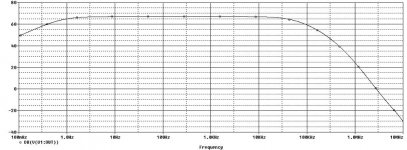
Ok i am done with the design of the RIIA.
The network is splitted 75uS in front as passive config and the other two as active.
I will attach the frequency response.
Spice show a very stable behaviour in frequency.
I will have to build the circuit to see if it is really stable or not.
Please any advice and tips are very welcome.
The network is splitted 75uS in front as passive config and the other two as active.
I will attach the frequency response.
Spice show a very stable behaviour in frequency.
I will have to build the circuit to see if it is really stable or not.
Please any advice and tips are very welcome.
Attachments
Greetings Stefano
Riaa looks very good. I hope you want mind a volt or two at output now and then. Or most of the time. You seem to ignore my post about the three choices but this won't cure the dc behaviour. A more sensible approach would be to discuss which of the three is least detrimental for sound.
Riaa looks very good. I hope you want mind a volt or two at output now and then. Or most of the time. You seem to ignore my post about the three choices but this won't cure the dc behaviour. A more sensible approach would be to discuss which of the three is least detrimental for sound.
Hi Analog,
no, of course, i haven't ignored your post.
I was wondering why you weren't posting anymore.
I have asked if ANY amplifier with DC gain more than one would lead to DC instability.
ehehe....of course i mind 2V of offset.
I mean i kinda of understand why the amplifier might have DC problems, since there is significant DC gain...any change in DC condition of the circuit due to the temperature will be greatly amplified at the output.
I am not positive this might happen, but if you say so i have to believe it.
That's alright we can consider an eventual cure for the DC instability.
1- you suggested DC coupling cap
2- servo control
3- large electrolytic on the signal RIAA (basically going back to the same think.
let me give you my opinion:
2- servo seems to be the less invasive; nevertheless once i was against coupling caps but now i don't like so much the idea of having an op amp interacting with the audio circuit as well.
1- output coupling caps: i would rather prefer not to have it at all, of course, but if i can use something like 1uf /100-200Kohm at the output without having issues with noise nor output impedance and if this would still offer a low cut off freq (using the same good teflon capi am planning on using) the solution would be painless: just my two cents.
I would also think that Servo would be cool.
What do you think accordingly with your experience is the best sounding solution:
having a very good output cap or a servo control (of course the servo would be muuuuuch cheaper)
Thank you analog for your instructive comments.
P.S. i still don't know how much noise Pk-Pk with the ONO") may anybody tell me that data for the sake of my curiosity?
may anybody tell me that data for the sake of my curiosity?
no, of course, i haven't ignored your post.
I was wondering why you weren't posting anymore.
I have asked if ANY amplifier with DC gain more than one would lead to DC instability.
ehehe....of course i mind 2V of offset.
I mean i kinda of understand why the amplifier might have DC problems, since there is significant DC gain...any change in DC condition of the circuit due to the temperature will be greatly amplified at the output.
I am not positive this might happen, but if you say so i have to believe it.
That's alright we can consider an eventual cure for the DC instability.
1- you suggested DC coupling cap
2- servo control
3- large electrolytic on the signal RIAA (basically going back to the same think.
let me give you my opinion:
2- servo seems to be the less invasive; nevertheless once i was against coupling caps but now i don't like so much the idea of having an op amp interacting with the audio circuit as well.
1- output coupling caps: i would rather prefer not to have it at all, of course, but if i can use something like 1uf /100-200Kohm at the output without having issues with noise nor output impedance and if this would still offer a low cut off freq (using the same good teflon capi am planning on using) the solution would be painless: just my two cents.
I would also think that Servo would be cool.
What do you think accordingly with your experience is the best sounding solution:
having a very good output cap or a servo control (of course the servo would be muuuuuch cheaper)
Thank you analog for your instructive comments.
P.S. i still don't know how much noise Pk-Pk with the ONO
may anybody tell me that data for the sake of my curiosity? Stefanoo said:I was wondering why you weren't posting anymore.
I don't have so many useful things to say anyway. It's more interesting why isn't anyone else posting. Seems like all those hundreds of Ono builders are completely satisfied
In my opinion there is a real lack of high quality phono stage designs on this forum. Somehow people seem perfectly happy to invest a few grand in a tt/arm/catridge(s) and even more in software and then listen through a hot-rodded NAD PP. Analogue magic.
The "real vendetta" thread can probably best illustrate the almost complete lack of interest in any more ambitious phono designs.
Enough ranting.
Don't have much experience with servos to judge but it probably is the best solution. The dc gain of the circuit is almost x1000. Too much even for a top quality monolithic opamp, let alone for such a simple discrete circuit.
Analog, i do agree with you.
I wonder why isn't anybody else posting..
Maybe i thought the 3d wasn't so exciting, i don't know.
People seems to be happy with the ONO.
Besides the fact of being happy or not, the point is not to copy NP design, the point for my viewpoint is to evolve design and come up with something different.
That's what a community is meant for.
This is just my view point.
For example: gary suggested the bootstrap cascode
you suggested to split the network
I suggested to modify the Current mirror
and other little details that have come along the way.
That is instructive and might create something interesting.
If more people would participate i am sure that the result would be even better.
Anyways, you suggest the Servo.
I don't absolutely have any kind of experience with Servos.
I don't usually like to add complexity even though it is neat.
A good simple DC coupling cap would do the option but a good one is expensive.
The idea that a feedback network would constantly adjust the circuit is something i don't like so much.
I have simulated the behavior with a 1uF 200Kohm at the output and the F cut is 1.1Hz which is definitely low enough i think.
I think i am going to try this circuit out.
I need to order parts from digikey and put everything on a protoboard and see how it goes with the DC.
I am planning on using monolithic BJT for the cascode and current mirror but i will get them along with the final parts (capacitors, connectors, resistors) but since everything would be order from america and shipping is expensive everything will have to come together.
Since the resistors i am going to use are Naked S102 and are expensive i will have to verify if ALL the gate stop resistors are REALLY required.
...till i won't build the circuit on the prototype i won't know...!
Analog any other tip and or suggestion is really welcome...so you and anybody there please, feel free to comment.
Edit:
BTW the preamp i have built some time ago is a DC coupled input and thus i would have no problem with the DC offset being blocked by the input stage of the preamp, right? Anyways, since it is nice to try it on other systems as well.....the piece of equipment might be "universal" and thus DC in general shouldn't be there
yeah I know.
That's what i meant to say before.
My only concern now is: ether a good Teflon coupling cap at the output or a servo are going to fix the DC .....BUT.....the amplifier itself is still going to be a not unity DC gain AND my question is:
is this going to be an issue or the amp is going to sound bad?
You would say...why would you think this? my train of thought is:
the ONO is an output DC coupled amp and STILL uses the 2 X 220uF cap on the network to guarantee unity DC gain and a decent bottom frequency response.
these two things seem to be redundant to me...but Mr. Pass is not the king of the redundancy and thus there must be a reason that i am not catching.
I don't know if i was able to explain my self enough.
Do you have any idea and/or opinion?
Stefanoo said:Since the resistors i am going to use are Naked S102 and are expensive i will have to verify if ALL the gate stop resistors are REALLY required.
Stefano,
I think you are moving in the right direction. I am not a fan of using servos. I think it's very hard to design them in a way that doesn't color the sound of the original circuit. The standard technique of using an op amp for the servo has this problem. The use of a DC blocking capacitor on the output is less objectionable than using a servo. Personally, I found the use of the 2 x 220uf a better choice than using an output capacitor but that is a personal preference. It would be interesting for you to experiment and see which one you prefer.
Regarding the expensive resistors, you don't need these everywhere. Many locations will be fine with standard good quality metal film resistors. For me, the critical location was the RIAA network and rather than use expensive resistors like the Vishays, I used good sounding surface mount Ta resistors. I like to think of these as a poor man's naked resistors since the case and endcaps are already removed. You just need good eyes and a steady hand and you can solder these into your network and get very good results.
---Gary
Stefanoo said:but Mr. Pass is not the king of the redundancy and thus there must be a reason that i am not catching.
It's an expensive commercial design. It has to be very reliable and not willingly blow other components. And Pass don't seem to get too neurotic about signal path capacitors. Maybe you are trying to turn the Ono into something it wasn't designed to be.
If you short the elecrolytics there will be a significant temperature dependent offset at output. A coupling cap will certainly block it but it will still eat from the available headroom. It may become a real problem with age .
GaryB said:
Stefano,
I think you are moving in the right direction. I am not a fan of using servos. I think it's very hard to design them in a way that doesn't color the sound of the original circuit. The standard technique of using an op amp for the servo has this problem. The use of a DC blocking capacitor on the output is less objectionable than using a servo. Personally, I found the use of the 2 x 220uf a better choice than using an output capacitor but that is a personal preference. It would be interesting for you to experiment and see which one you prefer.
Regarding the expensive resistors, you don't need these everywhere. Many locations will be fine with standard good quality metal film resistors. For me, the critical location was the RIAA network and rather than use expensive resistors like the Vishays, I used good sounding surface mount Ta resistors. I like to think of these as a poor man's naked resistors since the case and endcaps are already removed. You just need good eyes and a steady hand and you can solder these into your network and get very good results.
---Gary
I know the most sensitive locations are the RIAA network and the series resistor for the filter....but also the resistor at the output of the MC stage and the local feedback resistors of the 4 2SK170....
so...what's left are....few resistors
....What I was trying to say before is....how many gate stop resistors are REALLY needed? that was my question.
If i would reduce the gate stop resistors without compromising stability, it would be great!
(Still no one answered about output noise of the ONO: Gary, is it too much to ask you to connect the oscilloscope to the ONO and measure output noise?)
analog_sa said:
It's an expensive commercial design. It has to be very reliable and not willingly blow other components. And Pass don't seem to get too neurotic about signal path capacitors. Maybe you are trying to turn the Ono into something it wasn't designed to be.
If you short the elecrolytics there will be a significant temperature dependent offset at output. A coupling cap will certainly block it but it will still eat from the available headroom. It may become a real problem with age .
If you short the 220uF you will likely to have a weird frequency response
Did you try to short the electrolytic? is that what you have gotten (DC output temperature depency)?
i don't understand: why would a 200V rated film cap burn if it has few V across or become faulty with age? Also considering the output current that it will flow through the cap...do you still think there will be a considerable power dissipation on the cap?
I do agree with Gary though about Servos: most of the good piece of equipment I have listen to with a servo they have some colored sound...or at least it doesn't seem to be so natural as a Cap coupled circuit.
Anyways....i don't want to burn an expensive $90 film cap at the output
Stefanoo said:so...what's left are....few resistors
What I was trying to say before is....how many gate stop resistors are REALLY needed? that was my question.
If i would reduce the gate stop resistors without compromising stability, it would be great!
Stefano,
You absolutely don't need expensive resistors for the gate stop resistors. You might actually be better off using cheap carbon resistors since they are non-inductive, which is a good thing in this location.
(Still no one answered about output noise of the ONO: Gary, is it too much to ask you to connect the oscilloscope to the ONO and measure output noise?)
Apparently so
sorry  .
.---Gary
Stefanoo said:
If you short the 220uF you will likely to have a weird frequency response
Anyways....i don't want to burn an expensive $90 film cap at the output
Occassionally we seem to get into some severe miscommunication.
I though you intended to short the 220uF in your quest to get rid of caps and this is what we were discussing. Apparently not. Why weird frequency response?
Where did i mention that a cap will burn?
analog_sa said:
If you short the elecrolytics there will be a significant temperature dependent offset at output. A coupling cap will certainly block it but it will still eat from the available headroom. It may become a real problem with age .
You are right, there is some big miscommunication going on here
lets line up a little bit:
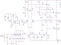
When i talk about the 2 X 220uF i am referring to the 2X 220uF on the RIAA (C1 and C41 original schematic)
On the schematic I have posted, as it's shown, I only use a coupling cap between MC and MM stage.
RIAA is split in two as you suggested.
This way i achieve a 0.001db theorical error till th amp doesn't start to fall off.
When you mentioned the DC stability issue, I am assuming you were referring to the 2 X 220uF C1 and C41 in the RIAA, right?
When you said: "If you short these two caps" you meant to say if you pull them off the circuit, right?
That is why I have said, if you pull these tow caps (C1/41) off the circuit and thus short the 100ohm (R21) resistor to ground, you will get a very bad RIAA equalization as those two capacitors also contribute to form the other 2 time constants.
You mentioned that without these two caps (like the circuit I have posted) it won't be possible to trim the output DC through the simple resistor anymore, since the DC output would be fluctuating due to temperature variation.
So i have included on the circuit an output coupling capacitor that will fix the DC at the output.
Nevertheless i understood you mentioned as quoted that the output coupling cap will be stressed and maybe become faulty.
Please let me know if i am still misunderstanding something here.
Stefanoo said:
That is why I have said, if you pull these tow caps (C1/41) off the circuit and thus short the 100ohm (R21) resistor to ground, you will get a very bad RIAA equalization as those two capacitors also contribute to form the other 2 time constants.
They don't contribute anything to riaa. As far as riaa is concerned they are a short circuit.
analog_sa said:They don't contribute anything to riaa. As far as riaa is concerned they are a short circuit.
If you want to get creative then you could turn this network into part of the RIAA. If you keep the 100ohm resistor and change the capacitor to an inductor then you could use this as part of the RIAA network but still have DC stability.
A quick calculation shows that the 50hz time constant needs a 318mh inductor and the 2110hz time constant needs a 7.32mh inductor. Either one of these would be possible and might make an interesting alternative to using capacitors. Putting a resistor in parallel with the inductor gives you one more knob to play with
---Gary
GaryB said:
If you keep the 100ohm resistor and change the capacitor to an inductor then you could use this as part of the RIAA network but still have DC stability.
Hi Gary. Sorry, bit i don't understand how the inductor would help dc stability. At dc it is pretty close to a short.
Oh, i guess you mean replacing the existing riaa network. This may actually work. Too bad good inductors are hard to find, difficult to use and expensive.
- Status
- This old topic is closed. If you want to reopen this topic, contact a moderator using the "Report Post" button.
- Home
- Amplifiers
- Pass Labs
- Aleph ONO working - belated thanks to pquadrat