Gary,
i have checked the datasheet and it shows a gate current of around 40pA for a VDS around 15V and id around 1.5mA.
This would lead to a really low value.
Strange, spice says that at the actual condition the gate current is 17.42nA that would lead to 3mV (i think a little bit too high!)
It must be the spice model for the 2sk389.
Thank you very much for your tip.
Stefanoo said:wait a second, we are out of synchronism
It's time to line up")
Stefano,
You are right - I am still confused over what parts you are changing or removing. It would be much clearer if you referred to the part numbers on the Pass ONO schematic. Then we could avoid all this confusion.
I did think that you were referring to removing C1 and C41 when you talked about removing the 2 x 220uf capacitors. This would be dangerous even if you apply the trick to remove the DC offset at the output. I am glad to hear that you are not doing this. And the value of these capacitors should not be decreased. The cut off frequency is set by R21 and gives a cutoff around 3hz. I like having the cut off frequency 10x lower than the minimum frequency where one will hear music, so 3hz seems about right.
For the output of the MC to the MM, you are right that you don't need a 220uf capacitor and using a smaller quality film capacitor and increasing the value of R20 are both good ideas.
---Gary
Hi Stefanoo
Thinking about your part selection, something crossed my mind. My process of building stuff is obviously different from yours. I always first build using garden variety parts and if the circuit shows some real promise go for exotics, substituting one part at a time and listening. Yes, i have plenty of time
The Ono didn't persuade me to use any exotics but if i had to, here's what i would do with the riaa caps. Getting these both accurate and good sounding is really tricky. Very few choices unless you buy a large number of caps and do your own matching. PC do match but i guess this is only to each other. An easier approach in your case would be to use a split riaa. As you don't intend using MM carts you can move the 75uS pole between the MC fet and the MM input as a passive first order filter. This will allow you to use practically any matched pair of caps. In addition it will very probably sound better.
Hi analog,
thank you for your comment.
In the reality when i build something, i always think about the best buck/performance parts to use on the eventual final version but still, i do build a cheap version.
I am actually going to shoot an order from digikey and other suppliers.
What i think about the original ono is:
it's a nice but very redundant...i mean not as simple as i would expect.
Maybe it's just lack of knowledge.
What i think Ono needs to improve on is:
1- a better PSU (a simple series regulator is not enough for a wide bandwidth MC phono stage, better regulation must be achieved)
2- the usage of too many coupling and especially electrolytic caps.
3- bottom response of the circuit is not so low and thus high coupling caps are required -> better RIAA eq network
that is what i think, besides the fact that for maximum performance the current mirror should be more refined (see Jung documentation on current source/mirror with experiments and results. I.E. Current surce with a led is good, but not great!)
O...setting my stupid thoughts aside...i am thinking about your suggestion.
I will have to think it through fully understand what you mean...try to implement it and see results.
With regard to PartConn, they do match at 1% within nominal value..so far so good from that side then.
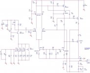
I am going to attach the RIAA circuit with the RIAA network i am using so any comment/suggestion is welcome.
Since the MC stage is DC coupled, there is no need for any Low pass filter and so the RIAA network can be very simple as shown.
I have just one doubt:
The simulation shows a little instability at around 10MHz.
By applying a LPFilter at the output (as shown on the Original Ono schematic) helps to keep it down.
What i was interested on is....since you guys already have the ono functional and running:
Have you ever tried to remove the low pass filter at the output and scope the output with your oscilloscope to see if any instability has been added or not?
Just one last curiosity: has anybody ever measured the Vpk-pk noise of the ONO at 71dB gain?
thank you for your comment.
In the reality when i build something, i always think about the best buck/performance parts to use on the eventual final version but still, i do build a cheap version.
I am actually going to shoot an order from digikey and other suppliers.
What i think about the original ono is:
it's a nice but very redundant...i mean not as simple as i would expect.
Maybe it's just lack of knowledge.
What i think Ono needs to improve on is:
1- a better PSU (a simple series regulator is not enough for a wide bandwidth MC phono stage, better regulation must be achieved)
2- the usage of too many coupling and especially electrolytic caps.
3- bottom response of the circuit is not so low and thus high coupling caps are required -> better RIAA eq network
that is what i think, besides the fact that for maximum performance the current mirror should be more refined (see Jung documentation on current source/mirror with experiments and results. I.E. Current surce with a led is good, but not great!)
O...setting my stupid thoughts aside...i am thinking about your suggestion.
I will have to think it through fully understand what you mean...try to implement it and see results.
With regard to PartConn, they do match at 1% within nominal value..so far so good from that side then.
I am going to attach the RIAA circuit with the RIAA network i am using so any comment/suggestion is welcome.
Since the MC stage is DC coupled, there is no need for any Low pass filter and so the RIAA network can be very simple as shown.
I have just one doubt:
The simulation shows a little instability at around 10MHz.
By applying a LPFilter at the output (as shown on the Original Ono schematic) helps to keep it down.
What i was interested on is....since you guys already have the ono functional and running:
Have you ever tried to remove the low pass filter at the output and scope the output with your oscilloscope to see if any instability has been added or not?
Just one last curiosity: has anybody ever measured the Vpk-pk noise of the ONO at 71dB gain?
Attachments
Have you ever tried to remove the low pass filter at the output and scope the output with your oscilloscope to see if any instability has been added or not?
OK, I am shooting from the hip here (as always), but me thinks the output filter is actually functioning as an additional time constant to compensate for the ominous Neumann constant, in which case I would certainly leave it in.
MRupp said:Very interesting suggestion. Am I right to assume that you would need to leave the feedback resistor for this time constant, i.e. R8, still in place in the MM stage so that you keep the overall gain?
Sorry, didn't explain properly. I would move the 75uS as a passive filter after the MC stage. Obviously the output impedance of the stage will be part of the timeconstant. The other two poles will remain active and the riaa parts will need to be recalculated. It will certainly make sense to keep R8 the same.
Hi Stefano
Didn't know PC match to 1% of nominal. Really good news. I would still split the riaa just because in my experience it sounds better that way. How will you manage the output offset? If you remove the feedback decoupling electrolytic you will need a cap at output.
Didn't notice any stability issues after removing the output filter.
MRupp said:
OK, I am shooting from the hip here (as always), but me thinks the output filter is actually functioning as an additional time constant to compensate for the ominous Neumann constant, in which case I would certainly leave it in.
sorry MPRup, the output filter inroduces a pole at around 150KHz and i think is intended to separate high frequency noise and cure eventual HF instabilty issues.
The newman you are talking about has to do with the Burning process where cut frequency is way beyond wideband capabilities of this circuit and that would imply a zero lag set with -3B at 3.18us but then you should also consider the roll-off freq of the amplifier used for the recording
just my two cents.
I am sure analog or others can better answer to this question.
analog_sa said:Hi Stefano
Didn't know PC match to 1% of nominal. Really good news. I would still split the riaa just because in my experience it sounds better that way. How will you manage the output offset? If you remove the feedback decoupling electrolytic you will need a cap at output.
Didn't notice any stability issues after removing the output filter.
DC is managed the same way i.e. through the resistor on the Differential amp.
Whay would you think that Offset might be an issue?
Maybe i am not catching something.
I still don't get it: why is it easier to get more precision by splitting the 2 networks?
Analog,
I am thinking about your idea i have the following questions:
would you place the 75uS pole (why 75uS and not the other?) at the output of the MC stage, but in cascade with the high pass filter (the filter that DC couples the MC to the MM), or you were thinking about a different way of doing this?
then it would work just putting the elementary cell pole-zero one the feedback path with the proper pole/zero settings and it would work?
I don't want to include the 220uF cap on the riaa network though
i will try to arrange the circuit simulate it and see how it goes.
Offset will be an issue. You have three choices: huge electrolytic in the feedback decoupling, output coupling cap or servo.
Advantage of the 75uS to be first is the reduction in high frequencies which supposedly makes the work of the following stage easier. I am not quite sure why, but splitting the correction always sounds better to me and allows for a wide range of capacitor values to be used.
You only need a series resistor after the MC stage and a cap to ground. The equivalent value will be determined by the load of the cascode and the input resistor of the next stage. Too high value of the series resistor will contribute to noise. Something like 10k will probably work fine. Not that it matters but the Vendetta correction is done like that.
analog,
sorry i don't understand if you are referring to the fact that the RIAA network i have posted would cause offset issues or, the offset issues will rise if the network is splitted or what?!
I have calculated the complete transfer function of the ONO and the 2 X 220uF don't have anything to do with the offset but they do control the gain of the stage and the first time constant at 3.7Hz that keeps up the LF gain.
Although i think this RIAA is tricky and complex and useless and can definitely be changed, it works pretty fine i am sure.
I understand that the 2 X 220uF and the 100ohm resistors form a 3.7Hz high pass filter and therefore they contribuite to have ahave less problems with DC on the feedback path, but once the DC is under control and regulated through the proper resistor, i don't see any problem.
Can you explain this a little bit better?
I understand that by splitting the 2 network will allow more precision on the RIAA curve, since the 75uS can be exactly implemented and there will be more choices to form 2 two terms filter.
BTW what is the vendetta correction?
I like the idea of having mixed together the Passive and active RIAA.
I think it is original
Stefanoo said:I think it is original
It is a very old concept. You can find the Vendetta schematic in the relevant thread.
If the dc gain is not unity there will be a significant offset at output due to temperature fluctuations even if you match the diff pair. Maybe a couple of volts. Irrespective of whether riaa is split or not. And even without any riaa.
sorry MPRup, the output filter inroduces a pole at around 150KHz and i think is intended to separate high frequency noise and cure eventual HF instabilty issues.
150 K ? If only I could trust your calculations
 P.S. I think I do know what the Neumann constant is there for ...
MRupp,
i don't understand, are you being sarcastic or what?
You can decide to trust my calculation or not.
For this time i will give you the complete formula so that you can verify directly but next time tou can validate my statement by calculating the formula your own, ok?
The transfer function of the output network is nothing less than a simple variation that a low pass filter:
H(s)= R82/(R28+R82) * 1/ (1+C8*R82*R28/(R28+R82))
Since R82>>R28 the formula simplifies and becomes
H(s)= 1/(1+C8*R28)
which...if you take your calculator and make your own nice calculation you'll see that it's pretty much what i have estimated without the usage of the calculator.
Simple, isn't it?
With regard to Newman's frequency:
if you know what it is, then why would you state that?
I mean it's ok to not know one thing...i mean.....look at me
Ciao.
analog_sa said:
It is a very old concept. You can find the Vendetta schematic in the relevant thread.
If the dc gain is not unity there will be a significant offset at output due to temperature fluctuations even if you match the diff pair. Maybe a couple of volts. Irrespective of whether riaa is split or not. And even without any riaa.
I didn't know that.
i mean....basically any operational amplifier on non-inverting configuration will have problem with output offset indeed?
i mean..i understand that the 2*220u will guarantee that the amplifier turns into a buffer follower at DC condition....but.....i didn't actually calculate the DC gain of the network.....now i am in difficulty

Do you have any advice...any tip to avoid to use such a high capacitor on the riaa and to avoid coupling caps at the output and servo control systems?
In fact jung's document on the RIAA amplification (i don't know if you have that) he says....."let's consider a circuit using a unity gain stable,wideband amplifier".
mmm...
Stefanoo said:i mean..i understand that the 2*220u will guarantee that the amplifier turns into a buffer follower at DC condition...now i am in difficulty
Do you have any advice...any tip to avoid to use such a high capacitor on the riaa and to avoid coupling caps at the output and servo control systems?
Stefano,
The 2 x 220uf capacitors aren't that bad, especially if you get a hold of the Blackgate 220uf 6.3v NX caps that I mentioned earlier. They are really good sounding caps. I recommend that you use them. With those capacitors you will not need an output capacitor (C7) if you've implemented the other change I suggested. Change R4 (4.02K) to a variable resistor and adjust the resistance for 0v at the output. This will be stable at less than 10mv variation if you're using the 220uf capacitors in the feedback network.
---Gary
Gary,
i know BG are good sounding!
I wouldn't still put them along with TEFLON cap on the RIAA.
It does NOT make sense to me.
Speaking of stability:
PSpice shows stability with both RIAA networks, so...maybe it's not taking in account some factors i guess.
Anyways....10mV of output DC is not what i am looking for.
DC should be around 1mV or so i guess.
Since you already have the ono working why don't you try to implement the network i have shown on the picture?...unless you have already tested it.
Would you be able to do that?
Can you tell me the output noise of the ono with the input shorted?
Stefanoo said:Since you already have the ono working why don't you try to implement the network i have shown on the picture?...unless you have already tested it.
Would you be able to do that?
Stefano,
Sorry but I won't have the time to do that experiment. There is too much going on getting ready for the holidays and I have too many other electronic projects waiting for my attention.
So I'll just have to be a sideline commentator watching your adventures.
---Gary
- Status
- This old topic is closed. If you want to reopen this topic, contact a moderator using the "Report Post" button.
- Home
- Amplifiers
- Pass Labs
- Aleph ONO working - belated thanks to pquadrat