Transformer Power Supply Ground
Hi,
when you say "ground reference from the power supply" are you referring to the two Bridge Rectifier(s) positive & negative outputs that are connected together along with connecting to the positive & negitive from the power supply capacitors, then all of these are connected to the Ground on the "front end pcb", I believe that this is what I have seen on the schematics ? A reply to this will help me out because connecting the "+" & "-" together with the ground seems counter intuitive to me, so it is responsible for my project taking so long to build because I dred reaching this point.
Thank You
Ian
When you check traces it shows that GND and SG are connected; SG means signal ground and is the same as GND.
I used two separate pads: one for input signal ground, the other to connect ground reference from the power supply.
I can't be much help in troubleshooting as I didn't built AJ-X yet, however the boards were tested and work fine if properly set up.
Hi,
when you say "ground reference from the power supply" are you referring to the two Bridge Rectifier(s) positive & negative outputs that are connected together along with connecting to the positive & negitive from the power supply capacitors, then all of these are connected to the Ground on the "front end pcb", I believe that this is what I have seen on the schematics ? A reply to this will help me out because connecting the "+" & "-" together with the ground seems counter intuitive to me, so it is responsible for my project taking so long to build because I dred reaching this point.
Thank You
Ian
scaiff001: tips. solder 1 or to points then clean tip with sponge. if it dont help fill the soldertip with solder before the sponge treatment. if this dont help I guess your tip is already broken. worked for me in 20 years both prof. and private. and I still have tips that are 10-15 years old and they are fine.
I find this rather handy for cleaning iron clad tips.
Buy Soldering Iron, Tips and Accessories TTC-LF Soldering iron tip cleaner/tinner Multicore 706397 online from RS for next day delivery.
Buy Soldering Iron, Tips and Accessories TTC-LF Soldering iron tip cleaner/tinner Multicore 706397 online from RS for next day delivery.
Heatsink Question
Hi all,
I'm contemplating building an Aleph-J and then converting it to a J-X channel once I'm comfortably experienced. A few questions before I jump in, though.
Dissipating around 30W per fet and, ideally, thermally connecting all of the fets (4) of one channel means that I would need to find a heatsink with
C/W = 30 deg. C / 120 watts / 1.25 (de-rating factor)
or
C/W = 0.2
Looking through the various heatsink manufacturers' websites nothing comes close, even at 12" lengths, unless I blow air across the sink. So here are the first questions:
1. How do you do it, do you just build using multiple widths of smaller heatsinks thus not end up thermally joining the fets?
2. Where do you draw the line, in the A-J's case would you go down to one-fet-one-sink?
HeatsinkUSA has a nice heatsink on offer with a C/W of 0.8. Going to a 12" length should yield a C/W of around 0.4.
3. How much would black anodizing further improve the C/W of this heatsink?
One thing I've been thinking of is building the case with some sort of chimney to generate a stack effect, like in buildings and chimneys, where rising hot air escaping from the top of the stack draws cool air in from the bottom. Building a case with the heatsink flat, fins pointing up, and covering the sink with a chimney assembly should cause an appreciable amount of flow. By my calculation a 20"-high chimney topping a 12"x12" heatsink (sealed on all but the fin edges) should cause a ~50cfm airflow. This assumes a heatsink temperature of 50 C, and an external temperature of 20 C. I can't be the first to think this would work, so:
4. What am I missing this with line of reasoning?
Being that I want to ultimately build a J-X I'd like to size the transformer to be good for two A-J channels or one A-JX. Antek offers a 600VA 18V toroid which, from comments here, will be under-powered. They also offer a 800VA 20V toroid which would probably be sufficient. Here's my PSUD simulation:
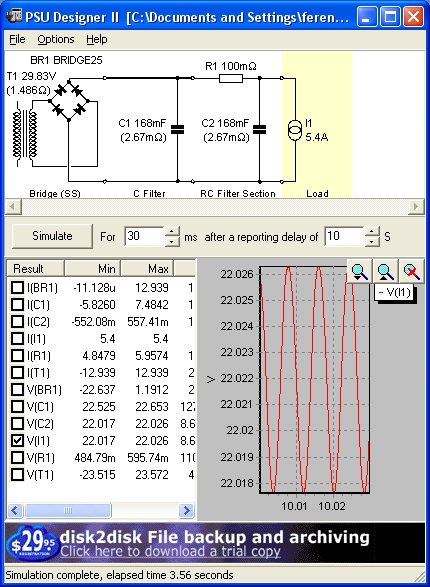
Note that the only reliable values in this simulation are the ESR values for the parallel caps (3x56mF). The transformer and current sink I'm not sure I configured correctly.
5. Can I use the 800VA/20V trafo in a CRC configuration without having to cascode (and learn how to do so, at least not now) the JFETs?
Thanks for any help and advice you can offer, it is much appreciated.
Jerry
Hi all,
I'm contemplating building an Aleph-J and then converting it to a J-X channel once I'm comfortably experienced. A few questions before I jump in, though.
Dissipating around 30W per fet and, ideally, thermally connecting all of the fets (4) of one channel means that I would need to find a heatsink with
C/W = 30 deg. C / 120 watts / 1.25 (de-rating factor)
or
C/W = 0.2
Looking through the various heatsink manufacturers' websites nothing comes close, even at 12" lengths, unless I blow air across the sink. So here are the first questions:
1. How do you do it, do you just build using multiple widths of smaller heatsinks thus not end up thermally joining the fets?
2. Where do you draw the line, in the A-J's case would you go down to one-fet-one-sink?
HeatsinkUSA has a nice heatsink on offer with a C/W of 0.8. Going to a 12" length should yield a C/W of around 0.4.
3. How much would black anodizing further improve the C/W of this heatsink?
One thing I've been thinking of is building the case with some sort of chimney to generate a stack effect, like in buildings and chimneys, where rising hot air escaping from the top of the stack draws cool air in from the bottom. Building a case with the heatsink flat, fins pointing up, and covering the sink with a chimney assembly should cause an appreciable amount of flow. By my calculation a 20"-high chimney topping a 12"x12" heatsink (sealed on all but the fin edges) should cause a ~50cfm airflow. This assumes a heatsink temperature of 50 C, and an external temperature of 20 C. I can't be the first to think this would work, so:
4. What am I missing this with line of reasoning?
Being that I want to ultimately build a J-X I'd like to size the transformer to be good for two A-J channels or one A-JX. Antek offers a 600VA 18V toroid which, from comments here, will be under-powered. They also offer a 800VA 20V toroid which would probably be sufficient. Here's my PSUD simulation:
Note that the only reliable values in this simulation are the ESR values for the parallel caps (3x56mF). The transformer and current sink I'm not sure I configured correctly.
5. Can I use the 800VA/20V trafo in a CRC configuration without having to cascode (and learn how to do so, at least not now) the JFETs?
Thanks for any help and advice you can offer, it is much appreciated.
Jerry
Attachments
Hi,
typically one uses (especially for the monoblocks) 2 heatsinks and puts one fet bank (the paralleled fets) on each of one, so - in case of the Aleph J - one pair per heatsink. Alternatively, contact a large heatsink manufacturer (like R-Theta) directly as these do offer 0.2 heatsinks (but typically not available at the large distributors).
Black anodizing mostly looks good and gives some isolation, no real benefit from a thermal point of view (heatsinks are about heat convection not heat radiation).
Last, with that amount of caps in the PSU you'll likely get problems with inrush currents and max diode currents. Either reduce them or think about soft-start.
Enjoy! Hannes
The heatsinks fins should be parallel to the airflow rising against it like a chimney.
The Black anodizing allows more radiative heat transfer to environment, but is dwarfed by the conductive heat transfer to air at these amp temps. Once you get into very high temps (1000F) then radiative starts to govern and really matter. When Radiative heat transfer is high enough, your bare skin will feel the heat, like sitting next to a campfire.
The Black anodizing allows more radiative heat transfer to environment, but is dwarfed by the conductive heat transfer to air at these amp temps. Once you get into very high temps (1000F) then radiative starts to govern and really matter. When Radiative heat transfer is high enough, your bare skin will feel the heat, like sitting next to a campfire.
typically one uses (especially for the monoblocks) 2 heatsinks and puts one fet bank (the paralleled fets) on each of one, so - in case of the Aleph J - one pair per heatsink. Alternatively, contact a large heatsink manufacturer (like R-Theta) directly as these do offer 0.2 heatsinks (but typically not available at the large distributors).
I assumed (wrongly, it seems) that since the four FETs in each A-J channel need to be matched to 0.1 Vgs they would benefit from being thermally connected. This is good news! It opens up a whole new set of possibilities...
Black anodizing mostly looks good and gives some isolation, no real benefit from a thermal point of view (heatsinks are about heat convection not heat radiation).
The heatsinks fins should be parallel to the airflow rising against it like a chimney.
The Black anodizing allows more radiative heat transfer to environment, but is dwarfed by the conductive heat transfer to air at these amp temps. Once you get into very high temps (1000F) then radiative starts to govern and really matter. When Radiative heat transfer is high enough, your bare skin will feel the heat, like sitting next to a campfire.
Interesting, so there is no real C/W-effect with black anodizing?
Last, with that amount of caps in the PSU you'll likely get problems with inrush currents and max diode currents. Either reduce them or think about soft-start.
I was thinking a CL-60 in series with each primary. Not enough?
Aleph-X PCB's
I group members,
Does anybody an address to buy PCB's to build the Aleph-X amplifier at a correct price?
I am interested in buy 3 of them") .
.
Thanks,
Victor
I assumed (wrongly, it seems) that since the four FETs in each A-J channel need to be matched to 0.1 Vgs they would benefit from being thermally connected. This is good news! It opens up a whole new set of possibilities...
Interesting, so there is no real C/W-effect with black anodizing?
I was thinking a CL-60 in series with each primary. Not enough?
I group members,
Does anybody an address to buy PCB's to build the Aleph-X amplifier at a correct price?
I am interested in buy 3 of them
.Thanks,
Victor
Does anybody an address to buy PCB's to build the Aleph-X amplifier at a correct price?
I believe that Peter Daniel has just made another batch of Aleph J-X boards available.
Contact him through his website here -- DIY Chip Amplifier Kits, PCB's, Components and Information.
The heatsinks fins should be parallel to the airflow rising against it like a chimney.
The Black anodizing allows more radiative heat transfer to environment, but is dwarfed by the conductive heat transfer to air at these amp temps. Once you get into very high temps (1000F) then radiative starts to govern and really matter. When Radiative heat transfer is high enough, your bare skin will feel the heat, like sitting next to a campfire.
^^ this
i understood the description as the fins ridges were pointing vertical, rather than the standard way so the length of the fin ran vertical, if you know what i mean. he was half way there, but not all the way unless i misunderstood
so there is no real C/W-effect with black anodizing?
Wait a year.
You went over my head Jacco...it won't be the first time, tho...
Compared to overall conductive and convective heat transfer, this is correct...some may disagree...
so there is no real C/W-effect with black anodizing?
Compared to overall conductive and convective heat transfer, this is correct...some may disagree...
Last edited:
^^ this
i understood the description as the fins ridges were pointing vertical, rather than the standard way so the length of the fin ran vertical, if you know what i mean. he was half way there, but not all the way unless i misunderstood
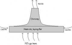
You understood correctly. What I was trying to describe was a structure where the heat rises up a chimney and draws cool air from underneath. Something like this (excuse the crude drawing):
The basic principle is the hot air within the heatsink/chimney structure want to escape out the top of the chimney. As this hot air escapes it draws in cool air from the sides of the heatsink that are open. These sides are normally the top and bottom of the heatsink when it is mounted more traditionally, i.e. you can see through them between the fins.
This technique is used in buildings where you want to take advantage of passive ventilation instead of pumping air through the structure using fans. I thought it may be applicable in this situation since the temperature differential is so high that you can create quite a high airflow with a reasonably short chimney.
In any case, I was just throwing the idea out there in case anyone had tried it and discounted it.
Regarding my transformer question, though, would a 20V transformer (dual secondary) produce over 24V if configured with CL-60 in series with its primaries, individual diodes for rectification (two bridges, one per rail) and CRC for filtering. Better yet, what values should I use in PSUD for:
(an explanation of how you derived these values would be great!)
- HFA25PB60PBF diodes
- Antek 8420 transformer
- The current draw for the current sink
Thanks!
Attachments
Wait a year.
I'm afraid I don't understand. Can you explain?
Thanks,
Jerry
Compared to overall conductive and convective heat transfer, this is correct...some may disagree...
Thanks, John. Counter-intuitive, I guess, since you would assume that emissivity is important in actually transferring the heat away from the aluminum to the surrounding air. This is good, though, since silver is more acceptable to my other half...
Take care,
Jerry
afraid
Anodizing is basically just rapid corrosion of aluminum, making the oxidation layer multiple times thicker than the natural protection skin.
Thermal conductivity of the oxide film is much lower than blank aluminum, so clean aluminum with a fresh oxide tan will be a better heatsink.
Aluminum corrosion doesn't stop, the oxide layer grows, e.g. due to sulphur content in the air.
Thickening rate is very slow though, so slow that even salt water (chloric) alloy hull boats can do without the paint job.
When i visited the marina last week i checked out the hull of an Ovni boat for pitting, stood on a cradle for the winter, example picture :
http://1.bp.blogspot.com/_ExteyBqJgYw/S7RHLT_9AVI/AAAAAAAAACU/QHQI_u49_ck/s1600/IMG_0876.JPG
Anodizing does more than adding a fat oxide jumpsuit over the heatsink, the surface is dyed by filling the pores in the corrosion layer, then it's sealed.
The oxide layer of plain aluminum is not sealed, growth of the corrosion layer may be extremely small in a year's time, but the pores can hold on to particles.
See e.g. lubrication of aluminum.
Heatsinks for fan blown setups are by standard non-anodized, become very dirty in time, and are difficult to clean.
I favor blown setups, can easily extract a thousand watts heat from a 8" x 5" cross section blower heatsink.
Me cheapskate, so i buy used thyristor duty heatsinks, prepping them for an audio career after retirement takes a sand blast, a plain housewife clean up doesn't cut it.
An anodized heatsink just takes a wipe with a cloth now and then, ask yourself which one will perform better after some time.
Btw, heatsinks are made of aluminum alloy (6000 series for extrusion), not plain stuff, difference.
(me into boats, so i favor 5059 and 5383
 )
)
Last edited:
Anodizing is basically just rapid corrosion of aluminum, making the oxidation layer multiple times thicker than the natural protection skin.
Thermal conductivity of the oxide film is much lower than blank aluminum, so clean aluminum with a fresh oxide tan will be a better heatsink.
Is this the reason behind sanding the anodized coating away before installing the FETs, to enable more and better heat transfer from the FET to the sink?
Anodizing does more than adding a fat oxide jumpsuit over the heatsink, the surface is dyed by filling the pores in the corrosion layer, then it's sealed.
The oxide layer of plain aluminum is not sealed, growth of the corrosion layer may be extremely small in a year's time, but the pores can hold on to particles.
...
An anodized heatsink just takes a wipe with a cloth now and then, ask yourself which one will perform better after some time.
So, in fact any color anodization will perform well at the temperatures we're dealing with here, it doesn't have to be black. The heatsink will stay cleaner and be easy to keep clean thus maintaining a high efficiency. Thanks, Jacco.
Jerry
Fan Blown Simulation
I took Jacco's advice regarding heatsinks and started simulating with fan-blown, high-fin-density, heatsinks. It's amazing how much dissipation you can get with this set up, even with low airflow values.
For simulating I used R-Tools from Mersen (formerly R-Theta) and it produced a whole report of the performance. One thing that struck me, though, is that despite the low heatsink temperatures at each Q (between 49 and 51 deg. C, using a SilPad 400 0.18), and the low temperature at the top of the sink (44 deg. C) the junction temperature it calculates is around 125 deg. C. I used an Rjc = 0.89 C/W value from the IRFP240 datasheet, and it assumes a 0.45 C in2/W value for the SilPad. I specified 30W of heat from each Q (total of 8, arranged like Peter's A-JX boards).
Should I be worried here? Is there something I may have missed or configured wrongly? I've attached the report if anyone wants to look at it.
Attachments
- Home
- Amplifiers
- Pass Labs
- Aleph J-X Amp Project