I did a lot more digging last night and today and I found some of my answers.
RS (output to sources) = 10k or 22k
RG (output to ground) = Min. 33R 3W to 5W for 4 Mosfets
High output Euvl uses 100R
100W Caddock TO247s.
Now with respect to the "Premium" components are there any suggestions as to what would benifit the upgrade and what I should not bother with. I have read that carbon resistors shift (as I would expect all types do) and I should not use them in a position that would be used to hold a bias. I am lost on that part but hope to sort it out with some help.
James
"The additional mosfet pair is for people who need more power; it's only an option but since the board size allowed it, why not keep it?"
I thought these jfets can load max two pairs of Mosfets .
For more Mosfets we (2x3) have to cascade jfets, dont we? javascript:smilie(' ')
')
Christian
I thought these jfets can load max two pairs of Mosfets .
For more Mosfets we (2x3) have to cascade jfets, dont we? javascript:smilie('
')Christian
It could, if it was enough space. You may still manage to drill some holes, if really needed.
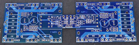
However, why complicate things, when the the X-Daughter board mounts directly into the pads on the two output boards (using pieces of wire)
Previously, there were complains that the boards were too small, now we have a single, full size assembly
However, why complicate things, when the the X-Daughter board mounts directly into the pads on the two output boards (using pieces of wire)
Previously, there were complains that the boards were too small, now we have a single, full size assembly
Attachments
I'm receiving some questions about X amp concept and advantage. Maybe those articles provide more info:
http://passlabs.com/pdf/articles/xa_paper.pdf
http://passlabs.com/pdf/product_lit/x_5-xa_5-amps.pdf
http://passlabs.com/pdf/articles/xa_paper.pdf
http://passlabs.com/pdf/product_lit/x_5-xa_5-amps.pdf
I used cut-off wires from film caps to mount the daughter board on my Zv4j. After several are soldered, it is sturdy enough not to need the mounting hardware.
http://www.diyaudio.com/forums/showthread.php?t=66397&highlight=Buffer+Blues&page=4
http://www.diyaudio.com/forums/showthread.php?t=66397&highlight=Buffer+Blues&page=4
Those Conrad heatsinks are fine for the standard version. One per channel.
Sorry, still confused by this...The conrad M35-151 are fine for one channel of Aleph-J but not the Aleph JX ? How many watts per channel do we need to dissipate for the Aleph JX
With 1.8A bias per side about 180 watts per ch.
Thanks Bill
The Conrad MF35-151 is good for about 107 Watts at 30deg rise. Since I already have them on hand I am consider using fans to increase the dissipation. Does anyone know how to calculate the additional benefit of the fan.
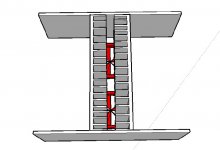
I am considering a chassis layout with the heatsinks fin to fin essentially creating a bit of a chimney with 2 fans pushing air through the bottom. Will this work? Any thoughts please share.
PS I just order these multi speed noctua fans that have a db range of 6-18dbs. http://www.quietpcusa.com/Noctua-NF-S12B-FLX-Quiet-PC-Fan-120mm-P561C68.aspx
Attachments

2sj74 pin config on board
Peter, sorry for prior post- I accidentally sent it midstream.
My question is, how should the 2sj74's be soldered to the board?
Holding the board vertically, the holes on the board look like this:
o o o
o o o o
I saw the picture of your populated board, but still can't see the pin configuration - any way you could graphically show what pin goes to what hole? I know this sounds like basic electronics for dummies, but please bear with me. Thanks!
-
Thanks Bill
The Conrad MF35-151 is good for about 107 Watts at 30deg rise. Since I already have them on hand I am consider using fans to increase the dissipation. Does anyone know how to calculate the additional benefit of the fan.
I am considering a chassis layout with the heatsinks fin to fin essentially creating a bit of a chimney with 2 fans pushing air through the bottom. Will this work? Any thoughts please share.
PS I just order these multi speed noctua fans that have a db range of 6-18dbs. http://www.quietpcusa.com/Noctua-NF-S12B-FLX-Quiet-PC-Fan-120mm-P561C68.aspx
I haven't used fans myself but Papa has said in the past they are very effective. I'd definitely use a couple thermostats (belt and suspenders) for safety in case you lose a fan.
- Home
- Amplifiers
- Pass Labs
- Aleph J-X Amp Project