xr000,
you are complaining about a hum but you tell nothing about your PSU.
Do you still have it when shorting the inputs?
My PSU are only two 10000uf capacities one channel!
This seems to be the main issue.
4x 15000 per channel are recommended.
I had tried 4x 12000 with success.
2x 10000 is definitely too small.
You could try 4x10000.
thank you very much!

You could go to DIY Chip Amplifier Kits, PCB's, Components and Information. and buy the big power supply boards he sells. He sells more than one style of power supply board so make sure you get the big ones at the bottom. $9 each if I recall. They are very good looking boards. Well layed out, cheap, and perfect for this application. They will accept 6 caps in a CRC configuration and you could get as much as 120,000uf in there, maybe more if any larger caps would fit. If you try this make sure that the diodes you use in his boards can handle the current. The board accepts TO-220 diodes.
Uriah
Uriah
Hi all,
is there a way to obtain bare Aleph J PCBs?
I would llike to build one following Wensan enhanced SRPP mods.
I (almost) do have all the parts but the PCBs
http://www.diyaudio.com/forums/pass-labs/37038-excellent-srpp-power-amp-mosfet-4.html#post1982249
is there a way to obtain bare Aleph J PCBs?
I would llike to build one following Wensan enhanced SRPP mods.
I (almost) do have all the parts but the PCBs
http://www.diyaudio.com/forums/pass-labs/37038-excellent-srpp-power-amp-mosfet-4.html#post1982249
Hi all,
is there a way to obtain bare Aleph J PCBs?
Try ebay.com
Q3 sucks some current from the jfet - and it tries to restore always the quiescent current - how should this work???
And Q4 amplifies the voltage on the sensing resistor - what for??? To much dissipation??? We could use higher resistor value there.
I don't like the bootstrapping - what for?
Maybe you could keep q4, set the idling current with it (see pass current source) and couple the signal of the sensing resistor direct. If you use a high resistor value to couple the Q4 signal to the gate, you could "overwrite" it with the signal from the sensing resistor.
(You need a zehner diode, bridged with a cap - because of the DC voltage drop require. You could use another zty for a current source for the zehner...)
But maybe, my understanding of Q3 is wrong, and Q4 improves all stuff... But what the hell bootstrapping is for - you only need it, if your driver normally requires a higher power supply, but you don't want to pay... ;-)
Regs, Dirk
HV. calm down.
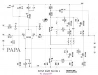
This is almost the aleph J schematic except two red points resistors which are wired differently.
The voltage across the sensing resistor modulates the current source from the emittor of
Q4 instead of from its base (Aleph) because, compared to aleph the sensing resistor voltage is phase opposite.
Though, Wensan would speak better than i do about this as beeing his own idea.
Last edited:
Sorry, I'm just getting exited if I don't understand things properly...
That you modulate on the emitter is maybe ok. But I still do not understand that you need the two unlabeled resistors... I still feel, we could drop all the ztx stuff and replace them with the J2 like solution. I cannot see any advantage - but maybe that is only because of my bad knowledge. So sorry if you got my comments in a rough way...
Dirk
The upper resistor is 68.2k like aleph J. I just erased the value by mistake.
The three tied are 0.47R
The resistor from base of Q4 to middle point is about 500R
I do not know precisely for the two last which i count to adjust experimentally for a8 ohm load, and /or to ask the help of Wensan.
I suggest you have a look at the Wensan thread: "Excellent SRPP power amp of MOSFET"
Last edited:
HV,
sorry, i did not mean to be rude.
The boostrap is as the Aleph j one.
The current source modulation is DC coupled.
My intention is to go one step towards J2..
This is SRPP after all...
http://www.diyaudio.com/forums/pass-labs/151909-firstwatt-j2-33.html#post1984161
sorry, i did not mean to be rude.
The boostrap is as the Aleph j one.
I cannot see any advantage
The current source modulation is DC coupled.
My intention is to go one step towards J2..
This is SRPP after all...
http://www.diyaudio.com/forums/pass-labs/151909-firstwatt-j2-33.html#post1984161
Last edited:
- Home
- Amplifiers
- Pass Labs
- Aleph J Schematic