
carpenter said:Hummm... what's the difference between the mini Aleph and the standard Aleph pcb?
None that I know of other than having the setup for a single set of FET's on board. I was able to fully trace through the Aleph J once I read the thread and got the corrected schematic. Still looks like maybe one small change.

carpenter said:Hummm... what's the difference between the mini Aleph and the standard Aleph pcb?
BrianGT's board has room for 1 pair of output fets on the main board and 2 small outboards that hold up to 3 more pairs. I agree with hayenc, it looks like the board can be used to make an Aleph J, and smaller and larger varieties as well!
Jim
I'll be working on a change sheet this weekend for using the BrianGT boards. So far it looks like leaving off parts, a jumper or two, and stretching the JFET leads to the TO-220 outline.
My first build will be with just the board and some IRFP250's in place of the dual IRFP240's. Keep it all on one board for now.
Craig
My first build will be with just the board and some IRFP250's in place of the dual IRFP240's. Keep it all on one board for now.
Craig
Wonderful. I can hardly wait to read results of your endeavor. I'm also curious with regards to the mods you're making to your pcb, and if that pcb is the same one that I have. Mine is 4" x 6" and just above seven resistors (RS2B) it reads: (first line) Class A Amplifier (second line) ALEPH CLONE (third line) not for commercial use. Is your board like this?
I have a slew of IRFP044N fets. They sim ok, hope they sound as good.
Here's wishing you all the best")
I have a slew of IRFP044N fets. They sim ok, hope they sound as good.
Here's wishing you all the best
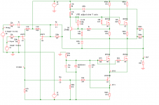
flg said:John, your input diff has no Isource?

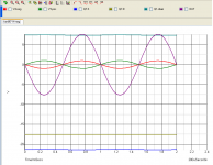
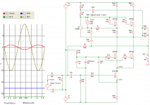
I'm getting a pretty good sine for not having a functioning input differential, wouldn't you say?
The sim also says I can also drop in the 2SK170, invert the Drain/Source resistor values and get the same effect.
Haha, you got me to thinking: I had way too much gain with the CCS. Without the CCS I'm just passing unamplified voltage through the jfet diff pair. I'll explore further.
Thanks flg!
carpenter said:
.... I'll explore further.
........
you're dumb ....... almost as ZM

Zen Mod said:
you're dumb ....... almost as ZM
Sometimes!!! (but you're not so dumb...)
Attachments
I just fired up one channel of my Aleph J built on Peter's A30 board with some modifications and it works, but the output is very low.
Could anyone please help me figure out what could be wrong?
Based on the AJ schematic posted by Papa, I measure 8.3V across R8 as expected, but across R7, I only get 3.5V instead of 4.3 and across the power resistor and mosfet, I get 3.187V (instead of the expected 4.3V) and about -112mV of DC offset.
I'm not reading any (almost nothing) voltage across the source resistors, so does that mean I'm getting 0 bias?
Any ideas where I can measure next or which parts to check? The heatsinks are stone cold, so I'm guessing I may have missed a part somewhere possible.
Thanks for any help
Stephen
- Home
- Amplifiers
- Pass Labs
- Aleph J Schematic