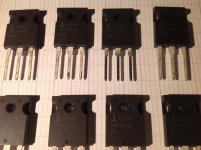
The Aleph transistors in one of the kits I sold will be (8) pc of IRF240, and they will have fairly large numbers written on the back of them, and those numbers are arbitrary, not actual Vgs values.
Should also be in a mylar ziplock bag about 3"x5". Tha bag may or may not have anything written on it depending on which batch of kits is was...
@ 6L6
My 8 pcs of IRFP240 from Aleph J kit are with large numbers
and are from two batches 4 pcs BMR and 4 pcs BLL.
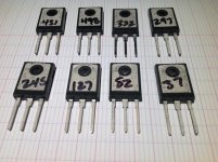
What part is for CCS and what part for audio signal ?
Kind regards
")

Attachments
OK ... I need help form the gurus ... I have tried everything and can't get rid of the hum!
As your grounding scheme seems implemented correctly, I would try the following (but I'm no guru):
-Move your input and output wires further away from the transformer to see if that makes a difference (in my pre-amp, even a distance of well over an inch between a very small transformer and the output wires resulted in significant hum). Another option, but more work: temporarily hook up your transformer outside of your case (prepare those terminal blocks)
-Check if it's not an issue further upstream (are the grounding schemes of your other components o.k. / do you use the same outlet / etc)
I got the hum reduced to where I cannot hear it at the listening position by moving wiring around inside the chassis. You have to get within about a foot of the speaker to hear it now. Good enough for me!
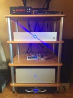
The Aleph and Pearl are all buttoned up. Still waiting on the faceplate back for the Mesmerize for the LCD window. Sounding great so far! Probably my favorite solid state amp I have heard to date (and I've heard a LOT)!
Question: I wired up the blue power LED to the V+ and GND on the universal PSU positive side with the appropriate resistor for 20mA and the LED flickers. It gets worse as the amp gets hot ... did I just get a cheap junk LED that is not heat tolerant? I would assume that rail is pretty steady and not fluctuating as the LED indicates. The LED's on the Aleph boards do not flicker.
Attachments
Last edited:
recalc for 3-5mA max
The guy I bought them from said 20mA ... But ... They are kinda bright! Ask the camera lens.

I am just stuffing my boards and have a question hopefully someone can answer.
I have a pair of jfets matched at 11 ma and one set at 16 ma. Matches are within .1 ma. I see that if using the recommended (around 8 ma) fets then r8 1k resistor with the 8.x volts across it give the 8 ma. I am assuming that the current splits thru q1a and q1b for approx. 4 ma per fet. That would be about 1/2 the 8 ma IDSS . So if I am using 16 ma fets do I have to set the current thru R8 (plus a pot in parallel) at around
16ma and therefore get about 1/2 the IDSS thru Q1A and Q1B( 8 ma in each leg). Am I on the right track here?
This is the only thing holding me back, everything else is going good. Thanks in advance for any thoughts on this.
-R8 will set current bias thru the diff pair jfet input stage; Voltage across R8 divided by R8 resistance should have twice the current the jfets were matched at; Putting a trimmer pot on R8 can get you to this value.
-R27 sets the Vgs + VRs of the Aleph Active CS mosfet; Active because of R24 and C3; R24 will adjust the Aleph ACS Gain -presently at 50% with 1.2k I think; It's been awhile since Alephs were the DIYers fashion statement (2003-2005?) but do a search and you'll find how the math or actual measurements were done. What the combination of R24 and C3 does is to provide feedback to the CS, thereby making it Active, and asks for more current if the load requires more. Think of loads with impedance dipping instantaneously with music's varying frequencies. This sets it apart from a Constant Current Source(CCS)
-R7 adjusts output offset to zero by matching the voltage Vgs+VRs of the output power mosfets (Q7, Q8) to the Vgs+VRs of the ACS mosfets (Q5, Q6) adjusted by R27. Here you can see the importance of matching Vgs of the power mosfets and also the Source resistors.
I am still confused about the R8 value needed for my build. As quoted above voltage across r8 divided by r8 resistance should have 2 times the current the fets were matched at? In my case of 16ma fets this means 32ma. That would mean 8.6V/32ma=268 ohms for r8. Is this correct?
I am still confused about the R8 value needed for my build. As quoted above voltage across r8 divided by r8 resistance should have 2 times the current the fets were matched at? In my case of 16ma fets this means 32ma. That would mean 8.6V/32ma=268 ohms for r8. Is this correct?
Hi, I think you want R8 around 1K. This limits the thermal dissipation of
the jfets and also gives the right voltage across R7 for proper operation
of the output mosfets Q7 and Q8.
Cheers,
Dennis
I am still confused about the R8 value needed for my build. As quoted above voltage across r8 divided by r8 resistance should have 2 times the current the fets were matched at? In my case of 16ma fets this means 32ma. That would mean 8.6V/32ma=268 ohms for r8. Is this correct?
R8 is a trimmer for setting the operating point of the input Jfet's CCS. It has very little effect on the actual current because the Zener is providing most of the reference.
Honestly, make R8 1K and don't worry about it. The input stage will be operating happily with a very wide range of Idss because the CCS will set the current, not the intrinsic Idss of the Jfet.
Well, I finally got my Aleph J assembled and powered up. No smoke, everything works. Initial bias voltage was 570mv before adjustment, around 100 something mv offset. Following 6L6's guide I set the biases for 350mv,zeroed the offsets and let it cook for 1/2 hour. Heat sinks were about 40C measured with an IR gun, the sinks are 2 piece per side, 190x165x32mm each(x4 total). Next I cranked up bias to 400mv,re-zeroed offset and covered for 1 hour. Bias had dropped to about 390mv after the hour so I re set it and re-zeroed the offst which had climbed to about 12mv. After the last adjustment the bias settled and the heat sinks measure 52c in a 22c room. Measured rms ripple at output of dc supply was 46mv both channels.I used an Antek 500va toroid with 8 18,000 uF Panasonic TU 25V caps. Measured rail voltages were 22.78 volts. So I have to give much credit to you folks who provided me guidance and answered my questions. Without your support I probably wouldn't have tackled this project and I'm sure there are others on this site that feel the same way.
R8 is a trimmer for setting the operating point of the input Jfet's CCS. It has very little effect on the actual current because the Zener is providing most of the reference.
Honestly, make R8 1K and don't worry about it. The input stage will be operating happily with a very wide range of Idss because the CCS will set the current, not the intrinsic Idss of the Jfet.
So, there's no need to put a trimmer on R8 and one can put a 1K resistor instead. Right?
Last edited:
It is depend on DC offset.So, there's no need to put a trimmer on R8 and one can put a 1K resistor instead. Right?
- Home
- Amplifiers
- Pass Labs
- Aleph J illustrated build guide