If your PSU design accommodates individual TO-220 rectifiers with 3 legs, as for example the Universal Power Supply PCB in the diyAudio store does, then the Field Effect Rectifiers from ST Microelectronics are appealing. Their forward voltage drop is amazingly low, thus they dissipate far less power and require less heatsinking. Have a look at their Vfwd at 25 amperes. Amazing!
_
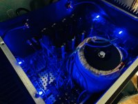
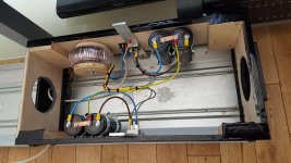
I’ve been working on making my AJ a dual mono setup, as well as moving from monolith GBPC bridge rectifiers to utilizing the discrete diyA boards. I took the opportunity to try out these FERD devices. I just wrapped things up this morning and have some wires to rearrange, but overall have been very pleased with the upgrade. I’d been running dual mono for a couple weeks with the GBPC devices, and hoping to do some critical listening and a few measurements later today to see what the discrete boards/FERDs bring to the table.
Attachments
Remember that “bias” in the Aleph is actually AC current gain, although increasing it does increase the total current and therefore bias. Generally speaking you are hearing the change in the current gain instead of the actual bias, as it has a more direct effect on distortion spectra.
Also speaking in generalities, Nelson’s suggested settings are almost always in the “sweet spot” for subjective sound quality. However, it’s absolutely up to you to experiment and find out what you like best.")
regarding "bias" sentence - well , actually not ; Aleph AC gain is solely set with value of R24 ( last schematic , few posts above) and it is not having much common with Iq of entire OS
OK, I agree, when you're fiddling with value of R27 (again that last schmtc) to increase Iq (say upping from 68K to 91K or so) , there is some influence on Aleph AC gain , but much lesser than there is change resulting from change of Iq ....... for AC gain values (and ratio) of R15,R24,R26 are still dominant
again , "bias" ........ I'm always trying to differentiate between biasing voltage and Iq - two interdependent things but still different ; in most cases speaking of one you're covering second , but in some cases they need to be taken with care and precision
Remember that “bias” in the Aleph is actually AC current gain...
Uhm, really? I'd say "bias" is DC bias and "gain" is how much the Aleph current source contributes to the AC output current. So, bias is DC and gain is AC.
The DC bias current is set by the current sense resistor in the Aleph current source (and considering the Vbe voltage of the BJT and the DC voltage across the BJT base resistor).
The AC gain is set by the resistor values in the Aleph current source. The best explanation for the gain and how to calculate the resistor values is in Nelsons patent (equation towards the end of column 3).
Jim has some pictures of a few current / distortion measurements on the first page of this thread.
Remember that “bias” in the Aleph is actually AC current gain, although increasing it does increase the total current and therefore bias. Generally speaking you are hearing the change in the current gain instead of the actual bias, as it has a more direct effect on distortion spectra.
Also speaking in generalities, Nelson’s suggested settings are almost always in the “sweet spot” for subjective sound quality. However, it’s absolutely up to you to experiment and find out what you like best.
Thanks guys. I remembered the measurements but was unable to find them...because they are located all the way at the end of page 1, and page 1 is very long. That is pretty much what I wanted to see. I will go to 1.1 A and see what happens.

OK, I agree, when you're fiddling with value of R27 (again that last schmtc) to increase Iq (say upping from 68K to 91K or so) , there is some influence on Aleph AC gain
I agree, and LTSpice will show such small changes, but I take comfort that the DC bias seems generally independent of the AC gain, both from simulations and the patent (mentioned above), as well as this comment:
You can trim the bias down arbitrarily without screwing around the ratios of other values.
For the FW Aleph J (Copyright 2005, General Amplifier), the current gain seems to be 20.83%, and it doesn't seem to be related to the quiescent current setting; two independent settings, influencing two independent things. One is placing the output stage in class A operation; the other is the amount of positive feedback (AC gain), that will improve the efficiency, but increase the distortions as well.
The easiest way to disable the current gain would be to "bypass" the 4 x 0.47 ohms resistors, with a (thick) wire link, and have that resistance sitting at 0.
The easiest way to disable the current gain would be to "bypass" the 4 x 0.47 ohms resistors, with a (thick) wire link, and have that resistance sitting at 0.
Last edited:
Remember .........
Disclaimer , strong one:
our 6L6 is one day going to build even more , learn even more and know even more about electronic , he's young and smart ;
on the other hand , I'll never going to learn how to fly , so go figure - who's in Double WinWin position here .....


...cheating with Elna's
?? Sounds interesting
?? Sounds interesting
at BAF 2019 , Pa gave those headphone amp kits (mini J2 or so ); while preparing bags for distribution on tables , someone of Boyz spotted that small 10uF ELna caps are missing in bags , even if packing was trice checked
Variac and Moi - we were ready to go to nearest electronic store to buy something as substitution , when 6L6 fully engaged his young brain ( knowing him , it wasn't even fully) and realized that we have same caps in H2 kit bags and we can take these (and these were meant for distribution tomorrow), while Pa can bring missing caps in time , to put them back in H2 bags
so , joke that Pa was cheating .
For the FW Aleph J (Copyright 2005, General Amplifier), the current gain seems to be 20.83%
I'm curious how you got this number.
Per NP, AC gain can be measured as follows;
I'm not sure that the quote addresses the question. I interpret it as wanting to know how to set the current gain of the Aleph current source, not the DC bias.
For the former, you generally want to set the gain so that the AC variation of the current source is about 1/2 the output current. It can be more or less, but 50% gives the optimal energy efficiency figure.
You will note in the Aleph schematics that the Base of the NPN transistor which controls the current source attaches to the output of the amplifier through an RC network. The value for C is set arbitrarily high so that it does not interfere with audio frequencies, and it is the value of R which is the most convenient spot to adjust the gain of the current source. For the purpose of this discussion, I'll call it R0.
If you set the amplifier driving a sine wave into a load (let's say 16 Vrms into 8 ohms at 100 Hz), you can measure the current variation of the gain N channel Mosfets (whose Sources attach through power resistors to the - supply rail) with a cheap AC voltmeter placed across one of these Source resistors. With R0 taken out of the circuit, you will get one AC value across the Source resistor (say 470 mV, for example). As you put a value for R0 in the circuit, this will decline, and when it measures 1/2 the value without R0, you have reached 50%. If it measures 1/4 the value, the current gain of the Aleph source is 75%, and this figure is too high for a standard Aleph. Most listeners like
the Alephs at 50% or lower, so I recommend between 50% and 100% of the AC voltage value compared with no R0.
Using LTSpice to simulate the published schematic (with R27 connected as shown), the AC current passing through a source resistor on a gain device is 370 mA (peak). That is, the current has an approx. 1.3 A DC component and a 370 mA (peak) AC component. Removing R24 - which is the equivalent of R0 - results in a 600 mA (peak) AC component.
Thus, the AC voltage with R24 is 62% of the voltage without R24, giving a current gain of 38%.
The current gain is sometimes expressed as a proportion of the output current. In the same simulation, the current into an 8 ohm load is 1.2 A (peak). Without any current gain, this is entirely supported by the AC component of the gain devices (2 x 600 mA). With the current gain, the gain devices supply 740 mA (2 x 370 mA), or 62% of the current, leaving 38% of the current to be supplied by the active current source.
I'm not sure where I got the 42% number earlier - I guess I picked it up from a few old posts by Bill Fuss (RIP) who mentioned it -
The Aleph J's AC current gain is set at around 42%, so quite a bit of output power can be picked up just going up to 50%.
It's close enough to 38% to probably include some component variation and simulation error.
As to changing the hookup of R27 - which changes the bias, if it remains 68.2k - the AC gain might change slightly, as mentioned
I think this mostly correct, but as the loop involved has limited gain, I experience slightly different values with different transistors and values of R19, bias current, and so on. That's why I always recommend measuring the value if you really want to know.As long as you don't replace the Source resistors to change the DC bias current the AC Current Gain stays the same.
The Spice model is attached for the curious
Attachments
Last edited:
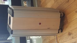
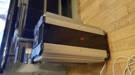
I've got a second pair of these heatsinks if anyone is interested. The end caps are part of the light fitting.
If only shipping from UK to US wasn't how it is.
I very much like it when I can well use something the life of which is viewed as over by some. I see many examples of this philosophy on diyAudio and applaud all who pursue it.
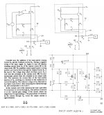
I considered Nelson's patent US5710522 for my calculation. I looked at this paper before I decided to build Aleph J, to figure out the "AC gain" everyone was talking about. The more I look at this AC gain, the more I realise its trade-offs... Is this amp a single-ended amp? That's the first question I've been asking myself recently. Furthermore, I know for sure that, by removing the 4 X 0.47ohm resistors, and replacing them with a nice piece of copper or silver ribbon on the PCB, will do wonders for my speakers. This could qualify as a second question, but to this one, I already know the answer.
The amp is an absolute stunner, but I firmly believe that, albeit the price I'll pay re efficiency, I will gain a lot in sound quality - by disabling the AC gain. But, it has to be disabled by removal of the 4 paralleled resistors - this will provide a two-fold benefit, compared to just removing the R24, for example.
I have tried to extract the important bits from the patent, and place the relevant (I hope!) Aleph J schematic -> to be able to do the simple calculation. So, I arrived at 20.83% "AC gain", provided by the CCS.
Attachments
I have tried to extract the important bits from the patent, and place the relevant (I hope!) Aleph J schematic -> to be able to do the simple calculation. So, I arrived at 20.83% "AC gain", provided by the CCS.
I think the math works out a little differently in the case of the Aleph J. When there are two parallel outputs, I believe "R_1" is defined as the parallel value of the source resistors. Making this change, we get the 42% number:

NP states in the patent that the equation is only approximate, so it makes sense that we would see slight variation in practice, so I feel comfortable with either 42% or 38%.
The difference between the simulation - 38% - and the simple formula could be attributed to the following explanation:
As I commented to macka privately, the formula ignores the transconductance of the Mosfets in the output
stage, using a simplified assumption that the transconductance is very high, and not dealing with parallel transistors.
This results in an apparently higher gain than found in the real circuit.
We can always check our work by applying the calculation to an Aleph 2 - we have on good authority that its current gain is around 50%:
Actual current gain on an Aleph 2 is close to 50%.
Last edited:
- Home
- Amplifiers
- Pass Labs
- Aleph J illustrated build guide