I share your concern about ambient temperatures in this part of the world. That's why I opted for the the 5U Deluxe to give the Aleph J components the easiest life possible.
I don't follow your comments about the Deluxe chassis and the UMS thread pattern. The website advertises that the Deluxe is drilled at the factory with the UMS thread pattern. I can confirm by direct inspection of the delivered article that the 5U has been pre-drilled with multiple threaded holes. I haven't measured them out to confirm that they match up but I'm not concerned that I'll have an issue.
Also, did you miss the option at the shop front to have UMS heatsinks supplied? See here:
UMS 40mm Heatsinks – diyAudio Store
I gather that's on offer for people who don't want the other odds and ends that you get with the chasis package.
When you were doing your own drilling, did you use the detail at:
https://cdn.shopify.com/s/files/1/1006/5046/files/universal-mounting-specification-v2.1.pdf
to work up a template to drill to?
Also, for info did you use a drill press or try your skills free hand?
He is talking about the 4U in 400 mm not having UMS pre drilled, but you could have it as an option. (there was a thread not long ago, come to think of it it required 5 to be bought but that was the Diy store, not modushop direct ) Your Deluxe 5U case will be drilled with the pattern.
The 4U deluxe would likely work as well, the additional length helps more with "roominess" inside the box. You may very well need the "Babysitter" invented by Zenmod. Your 5U chassis should be fine. Heatsink height seems to make more difference than width in terms of cooling. Again, with Babysitter, not an issue. The standard Deluxe 5U is 400 mm deep, and predrilled.
Babysitter for Papa's Koan
Russellc
Last edited:
Really. Is this with ideally located devices, or even with devices (output mosfets) located where forced by virtue of (in my case) DIY store boards? Seems like at some point this logic would fail, i.e. 1 inch tall heatsink 3 ft long? I suppose no more than heatsink 1 inch wide and 3 feet tall!. Well for the ten millionth time I guess I am wrong again...
Russellc
Russellc
Last edited:
Pass DIY Addict
Joined 2000
Paid Member
It is both cheaper and quicker to perform the real world experiment with the actual heatsinks and the actual transistors, than to attempt to build accurate software models of the entire apparatus. Then you need to run a time dependent transient 3D heat transfer software ($$$), capturing the results in some kind of video, showing software modeled temperature vs time. Ugh.
He is talking about the 4U in 400 mm not having UMS pre drilled, but you could have it as an option. (there was a thread not long ago, come to think of it it required 5 to be bought but that was the Diy store, not modushop direct ) Your Deluxe 5U case will be drilled with the pattern.
The 4U deluxe would likely work as well, the additional length helps more with "roominess" inside the box. You may very well need the "Babysitter" invented by Zenmod. Your 5U chassis should be fine. Heatsink height seems to make more difference than width in terms of cooling. Again, with Babysitter, not an issue. The standard Deluxe 5U is 400 mm deep, and predrilled.
Babysitter for Papa's Koan
Russellc
Thanks for that. Wasn't aware. Sounds like the suggestion is to have a contiguous 400 mm piece, rather 2 x 200 mm.
For additional cooling, another option is off the shelf kit. I'm aware that AC Infinity do various designs with thermostat capability. Never used them myself. Prefer to go for more heat sink than required. That said ZM's approach offers DIY kudos that's priceless.
Really. Is this with ideally located devices, or even with devices (output mosfets) located where forced by virtue of (in my case) DIY store boards? Seems like at some point this logic would fail, i.e. 1 inch tall heatsink 3 ft long? I suppose no more than heatsink 1 inch wide and 3 feet tall!. Well for the ten millionth time I guess I am wrong again...
Russellc
Well, I'm wrong with you.
With UMS spacing of the output mosfets a constant...
Applying the ol' heat rises maxim, seems to me that increasing height above the point source by x amount would be more effective than an increase of length by x amount.
Increase of output mosfet spacing causes me to visualize the fan shape of heat dissipation rising from the point source through the heat sink indicates that an increase of horizontal area may be more effective.
What do you know, everybody is right!

Maybe?
ZM; How did the output mosfet spacing on your original M25/SissySIT boards compare to the UMS spacing?
Pass DIY Addict
Joined 2000
Paid Member
Try this - You might not even need the diodes, if I recall they were added in case of an electrical fault.
Cutting the ground trace and inserting a 10R resistor greatly reduced, but did not completely eliminate, the hum. I also tried a 22R resistor, but there was no perceptible difference from 10R. I'll reinsert the amp into my audio chain in the morning and see how things go. Thanks again for the drawing.
I share your concern about ambient temperatures in this part of the world. That's why I opted for the the 5U Deluxe to give the Aleph J components the easiest life possible.
I don't follow your comments about the Deluxe chassis and the UMS thread pattern. The website advertises that the Deluxe is drilled at the factory with the UMS thread pattern. I can confirm by direct inspection of the delivered article that the 5U has been pre-drilled with multiple threaded holes. I haven't measured them out to confirm that they match up but I'm not concerned that I'll have an issue.
Also, did you miss the option at the shop front to have UMS heatsinks supplied? See here:
UMS 40mm Heatsinks – diyAudio Store
I gather that's on offer for people who don't want the other odds and ends that you get with the chasis package.
When you were doing your own drilling, did you use the detail at:
https://cdn.shopify.com/s/files/1/1006/5046/files/universal-mounting-specification-v2.1.pdf
to work up a template to drill to?
Also, for info did you use a drill press or try your skills free hand?
As others have said, the 4U/400 option is not available as a UMS pre-drilled sinks. I went to the Shop to try and order one, but the 4U 400 option was not available on the drop down list.
So I printed the UMS template out on my printer using the 100% option, stuck it on the sinks, punched on the marks, and drilled on my stand drill with higher quality aftermarket chuck, and still got thwarted. Drills just seem to love drifting in aluminium.
BTW, the widest extrusions I have seen to date are those 350 extrusions offered by Conrad in Australia. I have not yet seen any extrusions as wide as 400mm. I would LOVE to get my hands on those extrusions used by PASS in their XA products.
Nice. Thanks for the intel.
Well, I'm wrong with you.
With UMS spacing of the output mosfets a constant...
Applying the ol' heat rises maxim, seems to me that increasing height above the point source by x amount would be more effective than an increase of length by x amount.
Increase of output mosfet spacing causes me to visualize the fan shape of heat dissipation rising from the point source through the heat sink indicates that an increase of horizontal area may be more effective.
What do you know, everybody is right!
Maybe?
ZM; How did the output mosfet spacing on your original M25/SissySIT boards compare to the UMS spacing?
Mazeppa - The heat rises rule or maxim does not apply in a solid. Convection only occurs in a gas or liquid. In a solid the heat will conduct omnidirectionally depending on the thermal resistance of the solid.
Heatsinks do not work by conduction alone and the hot heatsink causes air to be heated between and near the fins and rise due to convection. My understanding is that in a tall heatsink the air flow will stagnate and be less than in a shorter sink thus reducing the convection for a taller sink of the same surface area. I believe this effect is related to the fin spacing and depth as well as heatsink height. I seem to remember some formulas out there on a vendor website for this but can’t recall where I saw them.
I'd have to dig up Uni references and the like to work up a first principles evaluation. Too much like hard work. Easier to use a calculator and do a comparative assessment.
Rod Elliot's website has some tools on offer including a heat sink calculator at:
ESP Download Page
I ran some numbers comparing a 4U with a 5U of a given depth equivalent to a Deluxe and then took the 4U and made it deeper by 100 mm. I found the latter two to be quite close in thermal performance. All depends on the basis you use of course, but if there's no deeper chassis on offer, then going taller makes sense. I'd need to count up the number of fins per unit length to confirm the calc but I still found it useful to use a consistent method to enable an objective comparison. Give it a go yourself and see what you come up with.
I'd also point out that there will be a proportion of the heat loss that's due to radiant heat. That's why heat sink fins are typically coloured black and not some other colour with a lower emissivity.
Heat movement, Convection conduction radiation
More fins per inch or cm is better and the thinner up to a point then they start to restrict air movement. That why high efficiency air conditioning condenser and high efficiency computer heat sinks use fans with fins as tight as 21 fins per inch. Yes vertical fins are better because of the natural stack affect that occurs as hot air rises. Than there is (mass) depending n the the material used, aluminum .copper ,silver. If you attached your transistors, mosfets to a black smiths anvil made out of aluminum .copper or silver is by far the best. You would feel almost no heat. They will run cool. Example of heat conduction if you take a spoon made out of iron or stainless steel And stir a cup of boiling water you can hold onto the end of the spoon handle all day long as you were sturing the boiling water. If your spoon was made out of aluminum or copper your fingertips will get burnt and three or four seconds do to conduction. If this spoon was made out of 100% pure silver your fingertips would get burnt in about a half a second. To cut down on cost and both materials and bulk in size and weight for transportation aluminum heat sinks base the part the transistor attaches to is usually someone around 10 millimeters or less it would be better if the base to be someone around 19 to 25 mm thick. Another example of mass . If you take a small finishing nails and strike a match and hold it under the flame of a match then immediately grab the nail with your fingertips what will happen. Now take that same match and hold it to a blacksmith anvil and then immediately put your finger over the spot where the flame was held you will feel nothing. Then there is radiation since heatis given off in a wavelength like light infrared. This is why the color black is used to absorb heat and white is used to reflect heat. It would be best if our heat sinks could be made out of copper but for commercial cost it’s too expensive and then on top of that you silver coat electroplate the copper. This is why Highend electronics radio gear and test equipment use copper plates internally to separate compartments and then silver coat them and it rejects RF interference and remove heat.
Mazeppa - The heat rises rule or maxim does not apply in a solid. Convection only occurs in a gas or liquid. In a solid the heat will conduct omnidirectionally depending on the thermal resistance of the solid.
Heatsinks do not work by conduction alone and the hot heatsink causes air to be heated between and near the fins and rise due to convection. My understanding is that in a tall heatsink the air flow will stagnate and be less than in a shorter sink thus reducing the convection for a taller sink of the same surface area. I believe this effect is related to the fin spacing and depth as well as heatsink height. I seem to remember some formulas out there on a vendor website for this but can’t recall where I saw them.
More fins per inch or cm is better and the thinner up to a point then they start to restrict air movement. That why high efficiency air conditioning condenser and high efficiency computer heat sinks use fans with fins as tight as 21 fins per inch. Yes vertical fins are better because of the natural stack affect that occurs as hot air rises. Than there is (mass) depending n the the material used, aluminum .copper ,silver. If you attached your transistors, mosfets to a black smiths anvil made out of aluminum .copper or silver is by far the best. You would feel almost no heat. They will run cool. Example of heat conduction if you take a spoon made out of iron or stainless steel And stir a cup of boiling water you can hold onto the end of the spoon handle all day long as you were sturing the boiling water. If your spoon was made out of aluminum or copper your fingertips will get burnt and three or four seconds do to conduction. If this spoon was made out of 100% pure silver your fingertips would get burnt in about a half a second. To cut down on cost and both materials and bulk in size and weight for transportation aluminum heat sinks base the part the transistor attaches to is usually someone around 10 millimeters or less it would be better if the base to be someone around 19 to 25 mm thick. Another example of mass . If you take a small finishing nails and strike a match and hold it under the flame of a match then immediately grab the nail with your fingertips what will happen. Now take that same match and hold it to a blacksmith anvil and then immediately put your finger over the spot where the flame was held you will feel nothing. Then there is radiation since heatis given off in a wavelength like light infrared. This is why the color black is used to absorb heat and white is used to reflect heat. It would be best if our heat sinks could be made out of copper but for commercial cost it’s too expensive and then on top of that you silver coat electroplate the copper. This is why Highend electronics radio gear and test equipment use copper plates internally to separate compartments and then silver coat them and it rejects RF interference and remove heat.
Last edited:
.....
ZM; How did the output mosfet spacing on your original M25/SissySIT boards compare to the UMS spacing?
Babelfish M25/SissySIT pcb is made for UMS
as I said, that means - ZM is Sissy ........ bending da knee , for Greeddy Boyz sake

Babelfish M25/SissySIT pcb is made for UMS
as I said, that means - ZM is Sissy ........ bending da knee , for Greeddy Boyz sake
Or ZM is just being nice guy.

Pass DIY Addict
Joined 2000
Paid Member
The next thing to try is star grounding, but I'm not sure that's possible given your PSU configuration... ? I'd need to see a few more photos of the rig wired up.
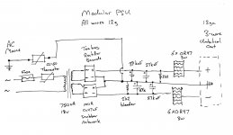
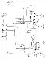
Here are two schematics of my present wiring: one for the modular PSU and the other for the Aleph-J chassis. It does not seem to make a difference if I add additional wires to ground the output sinks and/or the rectifier sinks to the AC Earth side of the grounding thermistor.
I am not yet convinced that my hum is an artifact of using a Y-cable or an iPad - this is how I have used my other amps: a40, ACA, F4, M2...
Attachments
Pass DIY Addict
Joined 2000
Paid Member
CL-60 on AC Hot leg = 11R cold, CL-60 on AC Ground = 13R cold. I measured with multiple meters, same reading all around. I also removed both CL-60s, straight connection to AC mains and straight connection to AC Earth. Same hum performance as before.
It also makes no difference if the main sinks are grounded to AC Earth or not. Same for rectifier sinks. It was interesting to connect my scope to the main sinks when they were not grounded: the sinks exhibit a ~1.0vAC sine wave with the music signal superimposed on the sine wave. The rectifier sinks also exhibit ~ 0.3vDC voltage rise when not grounded.
The hum is not very much, but clearly present with an ear up against the driver. It's practically gone with a distance over 1-2 feet. When one RCA is unplugged, the speaker is dead silent.
I'm getting tired of trying things here... maybe time to leave it alone for a while.
We had a listening test with the family (including 2 hifi aware sons) and my Aleph Js. There was agreement that the Aleph was slightly more detailed and had better definition of tonal colour (do I mean harmonics - not sure) but the class D reference was more theatrical and more emotional. Don't get me wrong, the Aleph is great but isn't a winner in all departments for me. I have wanted to try class A for years and am very glad I have but I don't think it will be staying - I haven't mentioned the heat / leccy bill. I am coming to the conclusion that good, well designed amps aren't terribly different in sound quality; find one that suits your taste and be happy
- Home
- Amplifiers
- Pass Labs
- Aleph J illustrated build guide