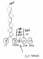
OK, just connected the Gate and Drain on the green connector that connects to the MOSFET, and the problem is gone.
Anybody care to explain WTF is going on? The resistance on the wire causing the issue?
I don't think so, and when I asked him Nelson didn't think so. It remains a mystery.
OK, just connected the Gate and Drain on the green connector that connects to the MOSFET, and the problem is gone.
Anybody care to explain WTF is going on? The resistance on the wire causing the issue?
oscillation, what else ?
even when just testing them , I'm always inserting gate resistor near mosfet gate pin
Thank you mentalgen.
Got sorted, went through all 25 MOSFETs in tube. Thing I learnt from this is that one must never assume all MOSFETs in tube comes from one substrate.
This is my Vgs distribution:
4.074
4.075
4.079
4.083
4.084
4.086
4.086
4.087
4.091
4.094
4.096
4.099
4.099
4.103
4.110
4.111
4.112
4.114
4.115
4.127
4.131
4.134
4.138
4.142
4.145
Last edited:
Pass DIY Addict
Joined 2000
Paid Member
I'm having a problem with hum in my completed Aleph-J and hoping someone can provide some insight for me.
I am using a modular power supply that I've used with my F4 and M2 with no problems, so I'm assuming that the problem lies with my Aleph-J, but I could be wrong. The power supply uses a single transformer with dual secondaries. Each secondary goes to a Tea-Bag rectifier board with diodes mounted on a small sink. From there, each rail goes through two caps (four in total) then through a bank of 6x0R47 3w resistors, then to the power umbilical. Once inside the amp, each channel has its own cap on the pos and neg rail (total of 4 caps inside the amp).
So here is the hum behavior. I am using a single test speaker and a Y-cable that plugs into my iPad for input.
-When both RCA inputs are open (no connection at all), I get a low level hum out of the speaker (only have a single test speaker)
-Single RCA input shorted, that channel is dead quiet
-With one RCA input connected, 1/8" jack disconnected, very low level hum
-One RCA input connected, 1/8" jack plugged into iPad, dead quiet
-With both RCA inputs connected, 1/8" jack disconnected: very low level hum
-With both RCA inputs connected, 1/8" jack plugged into iPad: more pronounced hum
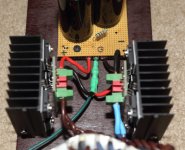
Images of my build are here
Closer image of the board is here Post #2935 in this thread.
Any ideas on what is causing this?
I am using a modular power supply that I've used with my F4 and M2 with no problems, so I'm assuming that the problem lies with my Aleph-J, but I could be wrong. The power supply uses a single transformer with dual secondaries. Each secondary goes to a Tea-Bag rectifier board with diodes mounted on a small sink. From there, each rail goes through two caps (four in total) then through a bank of 6x0R47 3w resistors, then to the power umbilical. Once inside the amp, each channel has its own cap on the pos and neg rail (total of 4 caps inside the amp).
So here is the hum behavior. I am using a single test speaker and a Y-cable that plugs into my iPad for input.
-When both RCA inputs are open (no connection at all), I get a low level hum out of the speaker (only have a single test speaker)
-Single RCA input shorted, that channel is dead quiet
-With one RCA input connected, 1/8" jack disconnected, very low level hum
-One RCA input connected, 1/8" jack plugged into iPad, dead quiet
-With both RCA inputs connected, 1/8" jack disconnected: very low level hum
-With both RCA inputs connected, 1/8" jack plugged into iPad: more pronounced hum
Images of my build are here
Closer image of the board is here Post #2935 in this thread.
Any ideas on what is causing this?
Last edited:
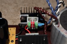
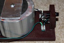
Do I see your input signal wire running parallel on top of your power wires ?
Through your photos I have the question of your input signal wires on top of your power wires ? Have you tried routing your power or your signal wire differently so they’re nowhere close to your power feed ?.
I'm having a problem with hum in my completed Aleph-J and hoping someone can provide some insight for me.
I am using a modular power supply that I've used with my F4 and M2 with no problems, so I'm assuming that the problem lies with my Aleph-J, but I could be wrong. The power supply uses a single transformer with dual secondaries. Each secondary goes to a Tea-Bag rectifier board with diodes mounted on a small sink. From there, each rail goes through two caps (four in total) then through a bank of 6x0R47 3w resistors, then to the power umbilical. Once inside the amp, each channel has its own cap on the pos and neg rail (total of 4 caps inside the amp).
So here is the hum behavior. I am using a single test speaker and a Y-cable that plugs into my iPad for input.
-When both RCA inputs are open (no connection at all), I get a low level hum out of the speaker (only have a single test speaker)
-Single RCA input shorted, that channel is dead quiet
-With one RCA input connected, 1/8" jack disconnected, very low level hum
-One RCA input connected, 1/8" jack plugged into iPad, dead quiet
-With both RCA inputs connected, 1/8" jack disconnected: very low level hum
-With both RCA inputs connected, 1/8" jack plugged into iPad: more pronounced hum
Images of my build are here
Closer image of the board is here Post #2935 in this thread.
Any ideas on what is causing this?
Through your photos I have the question of your input signal wires on top of your power wires ? Have you tried routing your power or your signal wire differently so they’re nowhere close to your power feed ?.
Pass DIY Addict
Joined 2000
Paid Member
ThermalAlchemy: In order to trouble shoot the amp, I have disassembled the chassis and all of the wires now have plenty of clearance. The hum issues remain. I am thinking it is something related to a ground loop because the hum is worst when the second RCA input jack is connected. This forms a loop because the ground from each channel meet before exiting the chassis at the power umbilical. Odd that this power supply does not cause any problems for my F4. This makes me think it is something in my Aleph-J. The sinks of the Aleph-J are grounded to each channel's PCB.
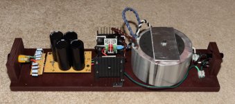
Here are some images and details for the external power supply.
AC in --> fuse --> CL-60 --> Rectifier boards --> Caps --> 2k Bleeder Resistors --> CRC Resistors (6x0R47) --> Power Umbilical
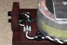
I made a jumper for the AC mains ground so I can lift it, direct connect it, put in a CL-60, or a diode bridge. No variation here makes a difference in the hum.
Here are some images and details for the external power supply.
AC in --> fuse --> CL-60 --> Rectifier boards --> Caps --> 2k Bleeder Resistors --> CRC Resistors (6x0R47) --> Power Umbilical
I made a jumper for the AC mains ground so I can lift it, direct connect it, put in a CL-60, or a diode bridge. No variation here makes a difference in the hum.
Attachments
Last edited:
I think you'd be better off with a 4th wire in your umbilical for PE (protective earth). When you put the ground lift in your new jumper, you really want the heat-sinks grounded to the power cord side of the ground lift.
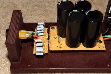
I also note that your input caps are large and inside a power loop (between -V and GND). You might be getting some inductive coupling there.
I also note that your input caps are large and inside a power loop (between -V and GND). You might be getting some inductive coupling there.
Pass DIY Addict
Joined 2000
Paid Member
Jeff: I was wondering if the hum was a function of my extra large Russian PIO input caps. The cases are metal and have a large surface area. The next thing I was going to try was replacing these with more traditional (and smaller) film caps. I hadn't considered the impacts of "where" the sinks were grounded in this case... Might be better to keep them isolated from signal ground. This is easy enough to experiment with using jumper wires.
Dennis: I'll try two shorting plugs and see what happens then.
Thanks for the suggestions, guys!
Dennis: I'll try two shorting plugs and see what happens then.
Thanks for the suggestions, guys!
No worries - shipping came to USD$57.16
The order included:
1 x Riser Panels - 2 pieces of 150mm x 90mm
1 x Riser Panels - 2 pieces of 150mm x 180mm
1 pair of black milled aluminum handles
1 set (4 pieces) of Anti-Vibration feet
The above really didn't count for much in terms of weight / bulk but in the interests of full disclosure, there you go.
For additional info, the above was marked on the con-note as a 16'ish kg shipping weight.
Does that cover it for you?
Yes thanks. I think I will need 2x 4U Deluxe chassis for my DiY Aleph J and DiY Sony VFET amps, but they are expensive including shipping.
However, I am not proficient in tooling a chassis nor do I own the required tools, so ordering them will be much, much more convenient in my situation.
Cheers,
Wouter
By the way, how do you plan to use the riser panels? Just curious.
W
Yes thanks. I think I will need 2x 4U Deluxe chassis for my DiY Aleph J and DiY Sony VFET amps, but they are expensive including shipping.
However, I am not proficient in tooling a chassis nor do I own the required tools, so ordering them will be much, much more convenient in my situation.
Cheers,
Wouter
The Modushop product hits the spot. I can understand why Jason has linked in with them. Applying a standardised mounting hole pattern to integrate with the PCBs is eminently good sense.
Even so, I wanted a couple of extra holes. Including one in a 22 mm size to mount a front panel push button switch. Like you, my toolshed was (at that time) limited and my original plan was to out source that job to the originating supplier. However, it became clear that while entirely doable, it would have been difficult to get it sorted and get the chassis delivered before Christmas.
So, I've gone the more expensive path and have a 16 speed 1/2 hp drill press sitting downstairs (fortunately I picked up an ex display unit for half price). So, I'm going through planning the job and procurement of additional odds and ends, such as:
- clamps to hold the front panel secure on the drill press table
- hole saw and pilot (done)
- soluble oil to use as cutting fluid (there's a universe of opinion on what's the best thing to use for various materials)
I've taken a philosophical view to play the long game. So, I'll be all set for the next job when that comes around in future. So, in that sense I'll be living out the diy audio dream.
The riser panels are loosely intended for mounting the soft start / speaker protection boards around the PSU transformer. I thought I'd get them thrown in and play Meccano with the 1:1 scale parts until I sussed out a layout that works / makes sense. If they don't get used, then no great cost incurred. When I get the plan properly laid out, I'll post some pics but that won't be for a while yet.
Wouter
I think the 4U De Lux will be too small to handle your Aussie ambient temps, unless you only want to use them in winter.
I went for the 4U/400, which I think is the minimum viable option for our southern hemisphere summers. The only problem is the fact that you can't get the 4U/400 heatsinks with the UMS templates drilled. And getting them drilled yourself is challenging, even with a decent drill.
I did mine this past week, and although I am a stickler for accuracy, I had trouble getting all 8 mounting screws to align with my Aleph J PCB. In the end I had to enlarge the holes to 4mm. And ordering a 5U De Lux chassis was going to work out to expensive, with the shipping all the way from Europe.
Pass DIY Addict
Joined 2000
Paid Member
...you really want the heat-sinks grounded to the power cord side of the ground lift. I also note that your input caps are large and inside a power loop (between -V and GND). You might be getting some inductive coupling there.
I moved the heatsink ground from the PCB to the AC side of the PSU and changed my grounding jumper to a CL-60 so there would be some isolation of signal ground and AC mains ground. No difference in hum: dead silent with a single RCA input, but hum with both plugged in. I grounded both of the small rectifier sinks - no difference here either.
I also changed out the big Russian PIOs for some smaller caps. No difference in hum behavior.
When I use two RCA shorting plugs as Dennis suggested, the amp stays dead silent. This is identical to the behavior with only a single shorting plug connected. The hum still shows up when both RCA jacks are used and the other end is connected to my iPad.
Doing some other poking around, I found a strange behavior with my CRC power filter when I measured for AC ripple. The caps in my outboard PSU are 39,000uF caps followed by 27,000uF caps then the resistor array.
Before resistor bank in outboard CRC: 127mV negative rail, 9mV on positive rail
After resistor in outboard CRC: 31mV negative rail, 9mV on positive rail
On amp board inside of amp: 18mV negative rail, 9mV on positive rail
The negative rail is behaving as I would expect with decreasing ripple, but something strange seems to be going on with the positive rail because AC ripple is very low after the first cap and never changes... Not sure what this means, but I'll swap out the cap bank and see if I get anything different.
...
-With both RCA inputs connected, 1/8" jack disconnected: very low level hum
-With both RCA inputs connected, 1/8" jack plugged into iPad: more pronounced hum
...
Going back to this, I'd say you have two different problems. The 1/8" jack only has a single ground, right? So the ground loop is formed when both RCA inputs are connected, whether the iPad is or not. Ergo the "very low level hum" is your ground loop.
The delta between "very low level hum" and "more pronounced hum" must be noise injected by the iPad (either on the signal lines or on the ground).
Try it with a different source and see what you get.
Wouter
I think the 4U De Lux will be too small to handle your Aussie ambient temps, unless you only want to use them in winter.
I went for the 4U/400, which I think is the minimum viable option for our southern hemisphere summers. The only problem is the fact that you can't get the 4U/400 heatsinks with the UMS templates drilled. And getting them drilled yourself is challenging, even with a decent drill.
I did mine this past week, and although I am a stickler for accuracy, I had trouble getting all 8 mounting screws to align with my Aleph J PCB. In the end I had to enlarge the holes to 4mm. And ordering a 5U De Lux chassis was going to work out to expensive, with the shipping all the way from Europe.
I share your concern about ambient temperatures in this part of the world. That's why I opted for the the 5U Deluxe to give the Aleph J components the easiest life possible.
I don't follow your comments about the Deluxe chassis and the UMS thread pattern. The website advertises that the Deluxe is drilled at the factory with the UMS thread pattern. I can confirm by direct inspection of the delivered article that the 5U has been pre-drilled with multiple threaded holes. I haven't measured them out to confirm that they match up but I'm not concerned that I'll have an issue.
Also, did you miss the option at the shop front to have UMS heatsinks supplied? See here:
UMS 40mm Heatsinks – diyAudio Store
I gather that's on offer for people who don't want the other odds and ends that you get with the chasis package.
When you were doing your own drilling, did you use the detail at:
https://cdn.shopify.com/s/files/1/1006/5046/files/universal-mounting-specification-v2.1.pdf
to work up a template to drill to?
Also, for info did you use a drill press or try your skills free hand?
- Home
- Amplifiers
- Pass Labs
- Aleph J illustrated build guide