I'm getting somewhere.
First of all the adjustment of WR2 problem. By chance I checked that the external volume control was in fact shorting the + input to GND. It wasn't so the + input was open circuit. Once that problem was sorted the 0V adjustment of WR2 became an easy task.
I'm setting up the 0V and output offset again. With the external volume control now connected correctly - YES HANDS UP - I GOOFED - This may solve the amplifier problem.
YES you can laugh. After all the effort in building a ladder stepped dual attenuator, I managed to get the Input and Output connections mixed up. I was feeding the input into wher the output should be and the output into where the input should be. I was wondering why the thing had such a strange volume profile.
GOOD LESSON LEARNT - CHECK, CHECK, CHECK and RECHECK your work.
Last edited:
For those watching and for Zen-Mod, the connections to the XLR connectors in post 73 have now been altered to the normal convention. This was not the problem as I made the interconnects to match the pre-amp wiring. Everything is now as per standard.

just don't lent your older ( not wired per standard) amplification gadgets to anyone .....

inform us about sound

Pumpkins still sound horrible - popping away like a bowl of cornpops.
After the issues with the PCBs I think I'll scrap these and stay with my home made Borbellys.
those are first of Pumpkin boards to have issues
I'll send you pair of new ones (thoroughly checked) , with my deepest apologies
in any case - If I send you schematic with all check points , you can check what can be wrong , even before new pcbs arrive at your door
what is arrangement in which you're using Pumpie right now ?
Did you adjust the offset in two directions, between one output and ground and between + and - output, otherwise you get clipping.
And you know the offset is not stable, it may change between + and - 100mV all the time.
But the sound is perfect! Better than stable offset.And you have the output cap!
Do not give up! You build nearly perfect things.... Relax and look later again....
Pump king is really good!
What do you mean by sound is popping away?
And you know the offset is not stable, it may change between + and - 100mV all the time.
But the sound is perfect! Better than stable offset.
And you have the output cap!Do not give up! You build nearly perfect things.... Relax and look later again....
Pump king is really good!
What do you mean by sound is popping away?
Finally I'm getting somewhere.
Originally I had the 100K volume pot. between the source and the Pumpkin and the Output of the Pumpkin connected directly to the 10K input impedance of the Power Amplifier.
I have reduced the noise CONSIDERABLY by moving the volume pot between the Pumpkin Output and the Power Amp Input.
With the volume at MAXIMUM and NO SIGNAL input I still get the NOISE though ???
Smario
Here is the finished article.
Please note that my volume Control And Input Selector are external.
Regards
Andy
Here is the finished article.
Please note that my volume Control And Input Selector are external.
An externally hosted image should be here but it was not working when we last tested it.
Regards
Andy
hm Andy,
putting the pot behind pumpkin is for sure a possiblity to reduce the noise.... but there is a mismatch between the pot 100k an the input 10k of your Aleph 4.
can you measure the gain of your pumpkin? with 50Hz and a Multimeter at least?
fine build, you have a hand for it!
putting the pot behind pumpkin is for sure a possiblity to reduce the noise.... but there is a mismatch between the pot 100k an the input 10k of your Aleph 4.
can you measure the gain of your pumpkin? with 50Hz and a Multimeter at least?
fine build, you have a hand for it!
Last edited:
...... The Output Offset is stable at 1-2mV or pretty much 0V.
offset between +out and -out stable to 1-2mV..... are you sure?
to be honest..... I cannot believe it,
please measure again for me.....if you want....thanks
offset between +out and -out stable to 1-2mV..... are you sure?
to be honest..... I cannot believe it,
thanks
With all inputs shorted, the Output Offset between +Out and -Out was happily sitting between 0.001 and 0.002V. The maximum I saw before adjusting WR1 was just over 1V.
By the way Im not using the Aleph 4 at the moment (It's not finished yet), I'm using a DIYGENE A700 which is a clone of one of the mark Levinson amplifiers. Which one I haven't worked out yet.
Anyone recognise what this has been cloned from ??
An externally hosted image should be here but it was not working when we last tested it.
Last edited:
Hi Andy,
if there were not the noise and popping in sound, I would congratulate you to your values...
at the moment I think these low values maybe a hint that something is not working right...
I hope that not jealousy is dictating my words.......
normally the thermal floating influences Q9 and Q10 of pumpkin and let us suffer from the considerable drift smario describes.....
you have really a difficult situation with your pumpkin and I hope that Zen Mod can give you more advice....
Did you make sure that the Shuntkys are accurately producing +/-36V. Mine are adjusted within mV of each other on all four rails. I don't know if this would make too much difference.
The two transformers are not one for each channel. They are arranged with their secondaries in series because I happened to have 2 x 20-0-20V transformers and needed 40-0-40V. The only point at which the 0V for each channel meets the other channel is at the 0V point between the transformers. PSU and 0V connections can be seen in the photo, each Pumpkin is connected by stout 50mm leads to the relevant connections on its Shuntky immediately adjacent to it. The AC connections can been seen in PINK. Each AC is paralleled with L & R channels so that the two Shuntkys share a single 40-0-40VAC supply.
0V at the transformers is also connected to CHASSIS with MAINS GROUND as can be seen with the GREEN wire that is waiting to be tucked away neatly.
The XLR connectors are all electrically isolated from CHASSIS. Care must be taken to ensure that the interconnects do NOT connect SIGNAL GROUND to CHASSIS.
This layout WORKS with NO MAINS HUM.
A preferred layout may have the GROUND of the XLR connectors connected to CHASSIS and DISCONNECTED at the Pumpkins. I have not tried this option.
Now that I am playing with Input and Output Impedances the Pumpkins are working perfectly. It just doesn't seem to like being at full output into the A700. In this instance the A700 has an input impedance of 10K and the Volume control places 100K across the output of the Pumpkin. Thus the Pumpkin is seeing an Output Impedance of ~10K.
Unusually the Volume control places a constant 100K across the Output of the Pumpkin, it is the Input Impedance of the Power Amplifier that is being varied.
22 of the 23 steps of the attenuator result in glorious silence from the speakers.
Unusually the Volume control places a constant 100K across the Output of the Pumpkin, it is the Input Impedance of the Power Amplifier that is being varied.
22 of the 23 steps of the attenuator result in glorious silence from the speakers.
you succeed ....
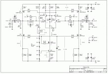
enclosed an older picture with voltage values from the original pumpkin thread, mind the difference around the LEDs in the circuit.... and I do not know how the two new resistors that should influence the drift influence the voltage values..
maybe Zen Mod has a newer picture....
enclosed an older picture with voltage values from the original pumpkin thread, mind the difference around the LEDs in the circuit.... and I do not know how the two new resistors that should influence the drift influence the voltage values..
maybe Zen Mod has a newer picture....
Attachments
- Status
- This old topic is closed. If you want to reopen this topic, contact a moderator using the "Report Post" button.
- Home
- Amplifiers
- Pass Labs
- Aleph 4 Strickly DIY Project Build