")
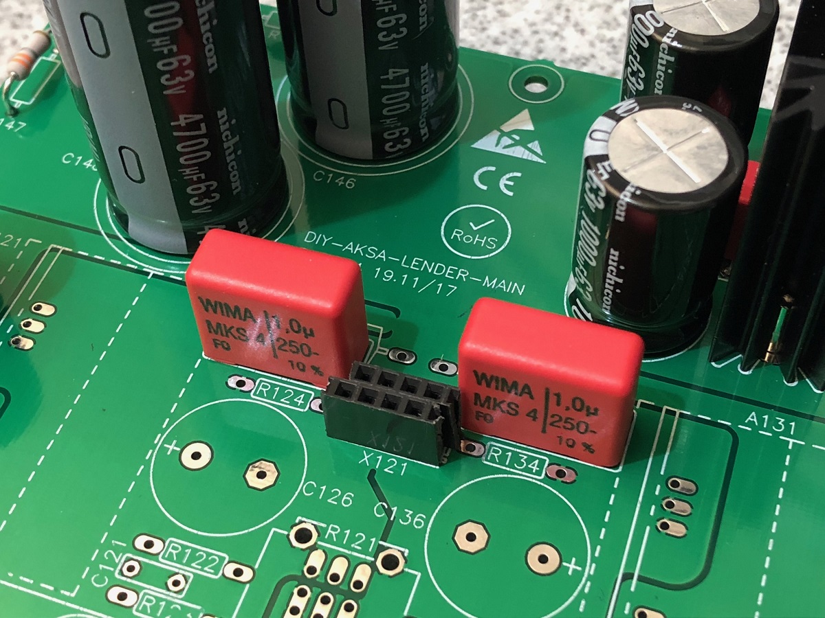
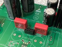
I think I found a cheap easy solution to the X121 connector: use standard PCB headers cut down to size, use two strips.
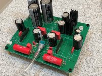
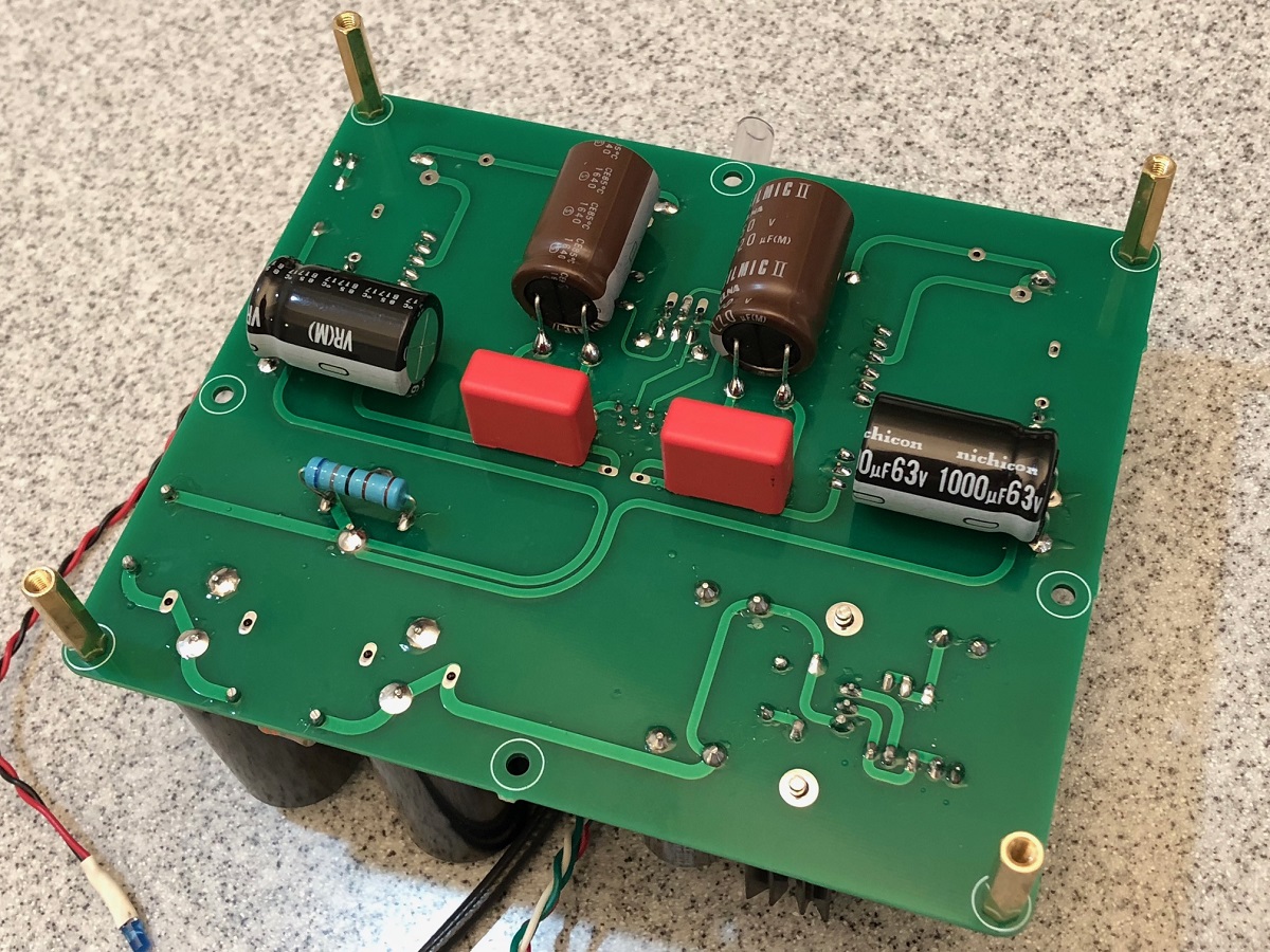
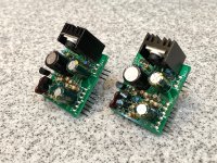
Here is my completed board number 2, built with the "good stuff" (all name brand caps) configured specifically to be a headphone amp (1000uF 63v output caps):
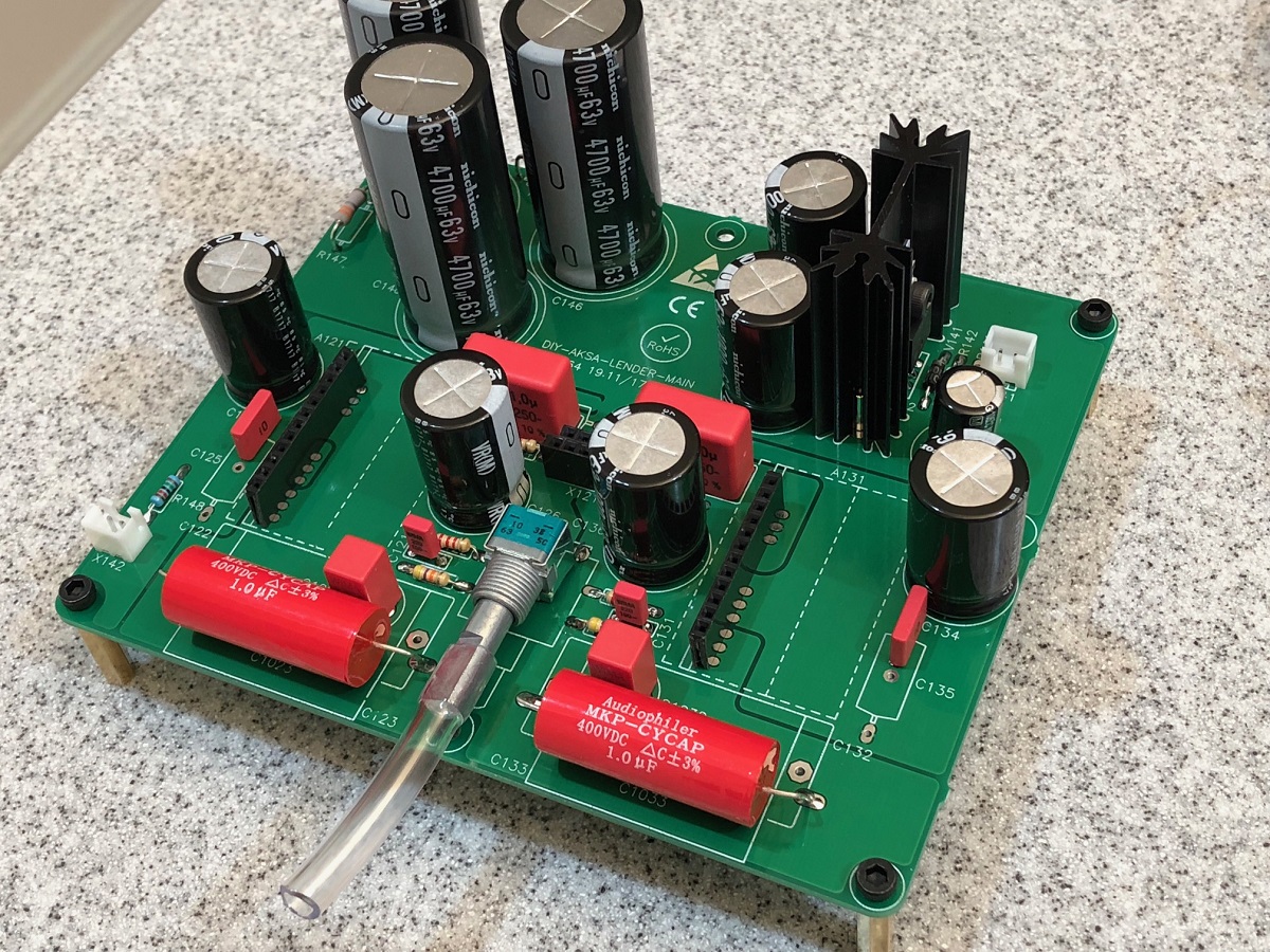
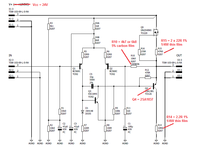
I will be using a TH daughterboard with a 2SA1837 in place of KSA1381 (note pins are reversed). Will bias at about 80mA and run from circa 30v Vcc for about 1.2W dissipation.
Here is my completed board number 2, built with the "good stuff" (all name brand caps) configured specifically to be a headphone amp (1000uF 63v output caps):
I will be using a TH daughterboard with a 2SA1837 in place of KSA1381 (note pins are reversed). Will bias at about 80mA and run from circa 30v Vcc for about 1.2W dissipation.
Attachments
Last edited:
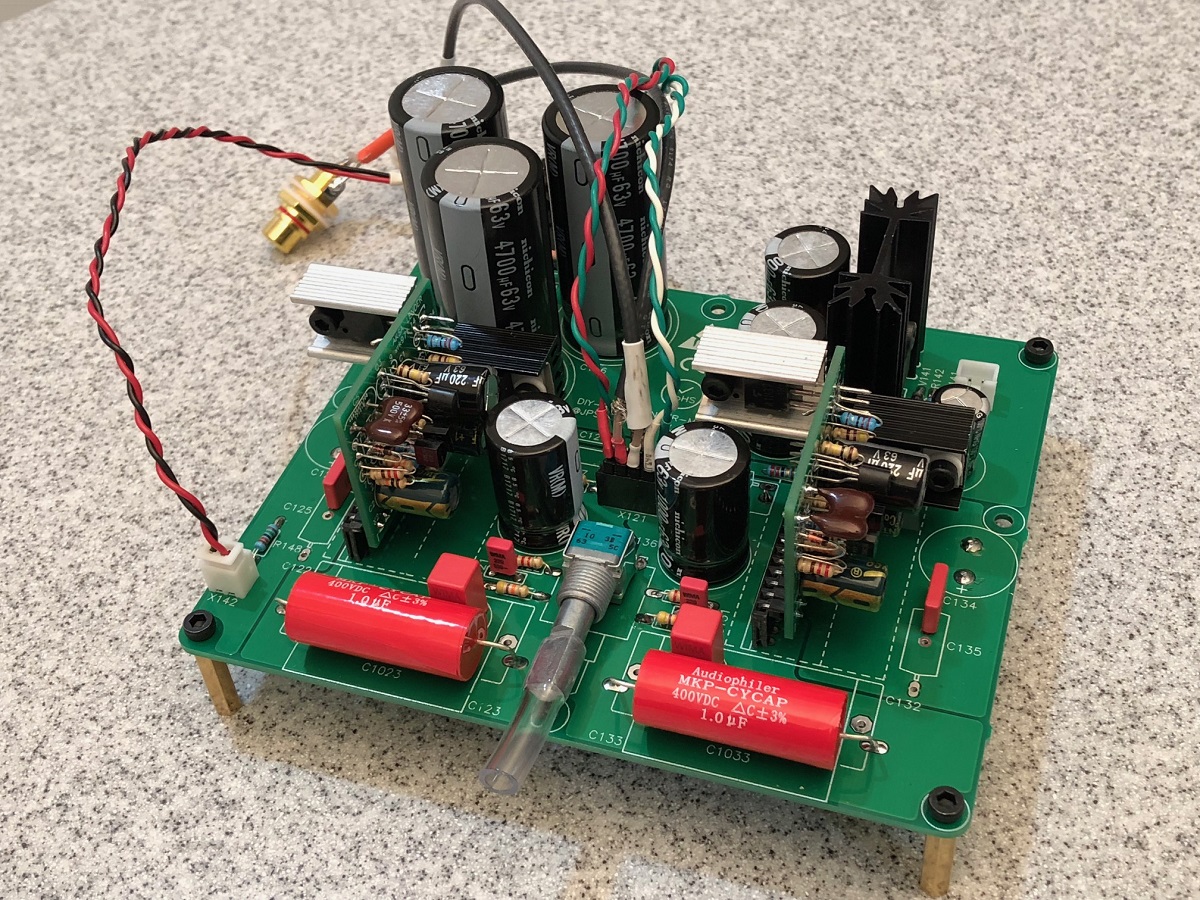
Aksa Lender Headphone amplifier (HPA) completed. I had to move some caps to the bottom to make room for the heatsinks. Running at 130mA for a toasty 1.56w dissipation on 2SA1837 and DN3540 ea. Note that 2SA1837 pins are reversed relative to KSA1381 so fits perfectly on backside of board for more clearance for heatsinks.
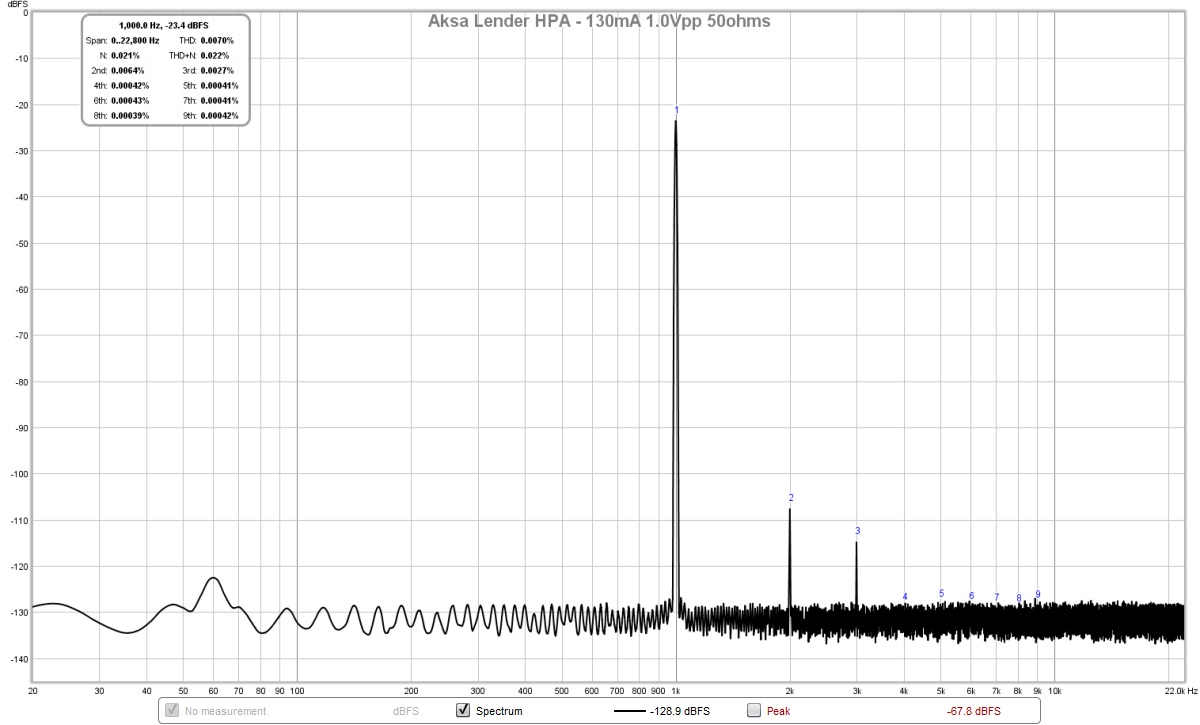
Sound is very nice. Powerful and clear - super quiet. Measurements to come later but it is about 0.006% THD for 1.0Vpp into 50ohms with mostly H2 and H3, as usual for Aksa Lender topology.

Edit - just got measurements done...
Measurements for 1.0Vpp into 50ohms, THD is coming in at 0.007% but very nice profile.
Will do some listening now for a while and report back later.
Sound is very nice. Powerful and clear - super quiet. Measurements to come later but it is about 0.006% THD for 1.0Vpp into 50ohms with mostly H2 and H3, as usual for Aksa Lender topology.
Edit - just got measurements done...
Measurements for 1.0Vpp into 50ohms, THD is coming in at 0.007% but very nice profile.
Will do some listening now for a while and report back later.
Attachments


Last edited:
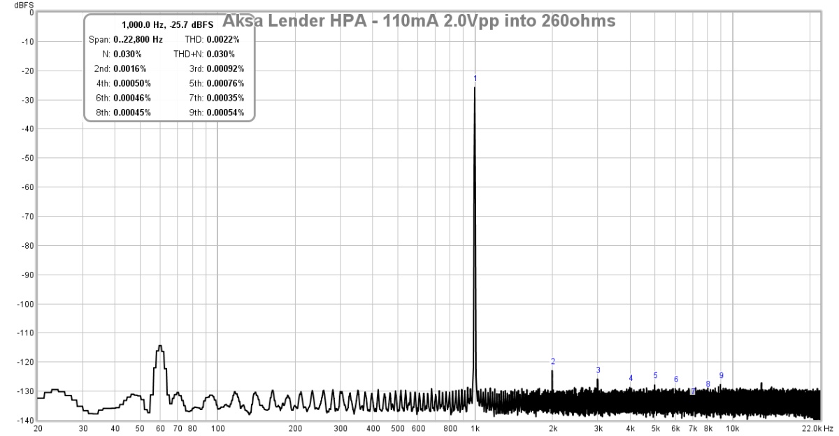
Listening with my DT880-250's now and sound is excellent. However, 13dB (4k7/1k) gain is not enough. Will need to increase to 6k8 I think. Probably can lower bias to about 105mA as 130mA is pretty hot on those small heatsinks. Right now using two 22ohm in parallel (11ohms) for R15 to set the bias. With the DN2540, the bias runs higher than the same resistor value for BSP129. A 33R and 22R parallel should give me 13.2 ohms for about the right lower bias setpoint. Another option when running lower bias is it allows higher Vcc for high impedance cans running higher gain.
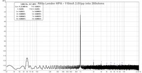
Increasing gain to 16.7dB via 6k8 feedback resistor is perfect for my DT880-250's they seem to be quite a bit lower sensitivity than the OB-1's. I dropped the bias down to 110mA, still runs pretty hot. Here is the FFT for 2.0Vpp into 260ohms. THD is about 0.0022% now, strange that driving a higher impedance load there is a higher 60Hz mains pickup somewhere. Not audible but just visible with the FFT.
Attachments
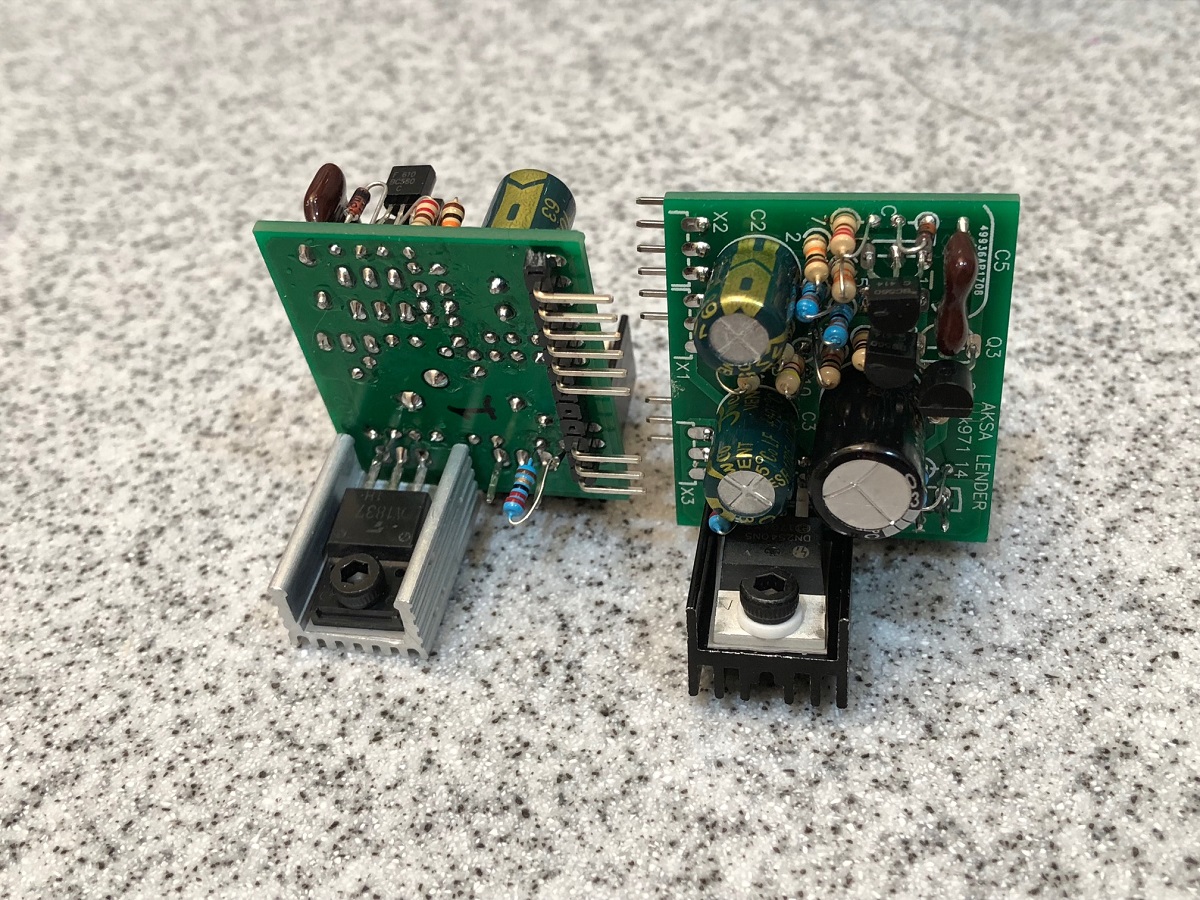
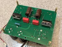
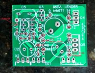
I just want to make sure people pay close attention to the orientation of the TH parts when stuffing the boards. It is so tight that the labels for the resistors can be confusing. The circle represents the resistor, and the little tail (like a tail on the letter Q) represents the wire lead from same resistor. The number of the resistor (R1, R2, etc) is shown, but the R is left off for brevity. If you put the wrong ones in or the tails in the wrong place, it won't work. I made my first one without issue but rushed the second set and got the wrong part and the wrong tail position on a couple of them (especially the ones on the left near the diode).
Please study my built unit here, tested working and see where the tails are and what values are used on the left placement.

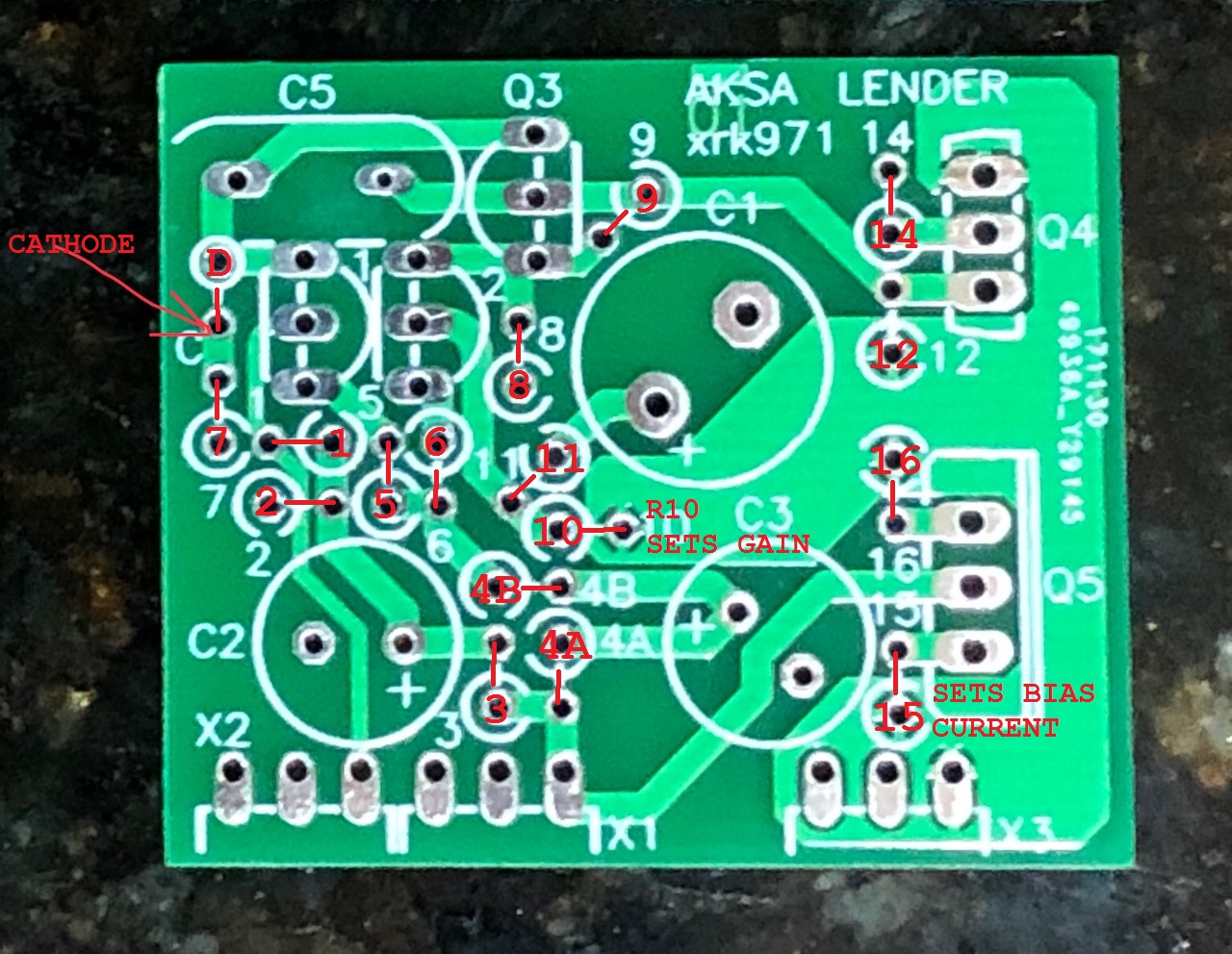
One other trick: if you place R10 and R15 on the backside, they will be in the clear and open to allow you to easily change them if you need to adjust gain or bias current. If you use 1% thin film for R15, the bias current set by the CCS will be almost perfect if the two DN2540's are from the same tube with similar Idss and Vgs. Alternatively, a multi-turn pot wired as a trimmer resistor could be stuffed into R15 to allow real-time adjustment.
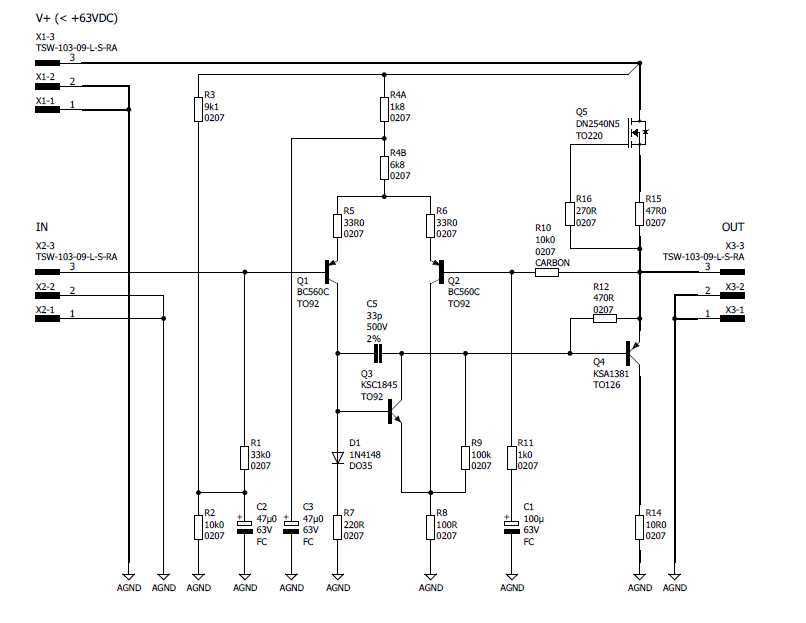
For a preamp, follow this schematic:
For a HPA, follow this schematic (if you have a 1% carbon film, use it here - 5% is ok if you manually match the resistors so they are within 1% before installing):
Please study my built unit here, tested working and see where the tails are and what values are used on the left placement.
One other trick: if you place R10 and R15 on the backside, they will be in the clear and open to allow you to easily change them if you need to adjust gain or bias current. If you use 1% thin film for R15, the bias current set by the CCS will be almost perfect if the two DN2540's are from the same tube with similar Idss and Vgs. Alternatively, a multi-turn pot wired as a trimmer resistor could be stuffed into R15 to allow real-time adjustment.
For a preamp, follow this schematic:
For a HPA, follow this schematic (if you have a 1% carbon film, use it here - 5% is ok if you manually match the resistors so they are within 1% before installing):
Attachments
Last edited:
- Home
- Group Buys
- AKSA's Lender Preamp with 40Vpp Ouput GB