X Can I post the final PC board layout for the BigBoy with the regular heatsink. I did spend a couple hours until I finished it.
Maybe someone would be interested to build wit regular heatsink or fan assisted heatsink.
I do not want to post the final without your permission.")
Maybe someone would be interested to build wit regular heatsink or fan assisted heatsink.
I do not want to post the final without your permission.
X Can I post the final PC board layout for the BigBoy with the regular heatsink. I did spend a couple hours until I finished it.
Maybe someone would be interested to build wit regular heatsink or fan assisted heatsink.
I do not want to post the final without your permission.
Sure, please do - JPS64 is still working on his layout so if you have one now, that's fine. I guess it is not tested yet?
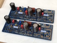
I managed to get this far with stuffing the 20W PCB, everything except the MOSFETs. I am missing 0.33R Panasonic metal thin film resistors at R131 and R132 (parallel qnty 2), so using 0.47R and 0.22R just to see if the amp will fire up properly. I am also using fixed resistors at R124 and R127. Also a 13nF MLCC at C112 since I do not have a 10nF film cap yet.
I think polarity of optional C102 electrolytic is reversed. Positive should face the LTP input base.
I matched the Hfe of the KSA992 LTP to the exact digit (3 significant places) with transistor tester. Then used shrink tube to thermally bond them together.
Using spade connectors on power input and speaker output. JST 2-pin jack for audio input. Panasonic 3.3uF 250V MKT cap bypassing the 10uF 35v Silmic II on input. C122 and C128 are 220uF 50V Silmic II. C111 is Nichicon 1000uF 63v cap.
Attachments
No is not tested yet (not even etched).Sure, please do - JPS64 is still working on his layout so if you have one now, that's fine. I guess it is not tested yet?
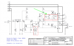
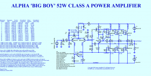
These layout with 3 pairs power mosfets! For the 52W.
For LTP I (T1 & T2)picked Hitachi 2SA872A that were the closest to the DMMT5401, and (T5) is a BC550C.
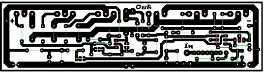
I draw my layout with paint and use color codes for the components
Red semiconductors
Green resistors
Blue capacitors
Yellow trimmers
Purple diodes
Grey jumpers
Any question, please let me know.
Tha black already mirror image, printer set up 75% for iron transfer.
Attachments
I managed to get this far with stuffing the 20W PCB, everything except the MOSFETs.
Now that was brutally quick...
No is not tested yet (not even etched).
For LTP I (T1 & T2)picked Hitachi 2SA872A that were the closest to the DMMT5401, and (T5) is a BC550C.
I draw my layout with paint and use color codes for the components
Red semiconductors
Green resistors
Blue capacitors
Yellow trimmers
Purple diodes
Grey jumpers
Any question, please let me know.
Tha black already mirror image, printer set up 75% for iron transfer.
Thanks, Gaborbela. Very nice. Can you please post higher resolution bitmap and include a stuffing guide picture with part outlines and labels on top of traces? I’m afraid without labels of some sort, mistakes are very easy to make.
Thanks,
X
Ok, I converted to JPEG file, I use (when I work Bitmap, easier to work with that and that can be posted an only smaller picture because of higher resolution.
When I convert it some discoloration especially the blue and red color but still acceptable quality.
When I have time I will put the part number next to each components (lines), it will make easier!
When I convert it some discoloration especially the blue and red color but still acceptable quality.
When I have time I will put the part number next to each components (lines), it will make easier!
Attachments
Last edited:
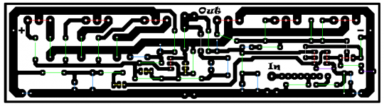
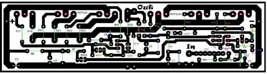
Here we go with the parts number from the schematics BigBoy.
That two (optional) trimmer at the middle was borrowed to this layout, I hope that is correct because you did not mark them just mentioned somewhere as an option. Next, to each electrolytic capacitors, there is a 100nF or 1uF foil capacitors. The two question mark only OPTIONAL capacitors.
Please, someone, go over the layout for double check! Thank you
I will pot the only black to NOT the mirror image. Please use the mirror image for Iron transfer!
That two (optional) trimmer at the middle was borrowed to this layout, I hope that is correct because you did not mark them just mentioned somewhere as an option. Next, to each electrolytic capacitors, there is a 100nF or 1uF foil capacitors. The two question mark only OPTIONAL capacitors.
Please, someone, go over the layout for double check! Thank you
I will pot the only black to NOT the mirror image. Please use the mirror
image for Iron transfer!Attachments
Last edited:
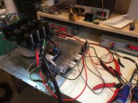
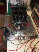
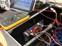
Progress but slow. I just pulled the Aleph J out of the 4U Dissipante UMS case. The 400VA 18vac trafo and F6 +/-24v PSU is already in place. All connections are spade connectors so that will be easy. The audio input is currently screw terminals is need to switch to JST 2.5mm pitch. Need to estimate location of bend angle on mosfet pins to solder approximately in place. The UMS standoff positions are a perfect fit. This is a remarkably compact Class A amp board.
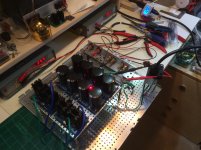
I got my power supply wired up, temporarily, and installed into a prototype chassis plate.
Unloaded the power supply is putting out ~25v per rail.
A few quick pics, please ignore the messy bench.
Unloaded the power supply is putting out ~25v per rail.
A few quick pics, please ignore the messy bench.
Attachments
Jwjarch,
Yes, 5U is optimal. For me, “you go to war with the army you got”
Pcgab,
That PSU looks great. I like the multi deck approach and angle aluminum is great for panel mounted jacks. What does that soft start board do and how does it work? That bench actually looks really neat. I see we have some of the same red handled tools.
I have NTC thermistors on the primaries of my trafo per Pass F6 PSU design.
Thanks, I'm lucky enough to have 2 benches in an 'L' there in my home office, I'm in the process of re-arranging some shelves, adding more shelves, etc. so it's currently messier than I prefer.
The chassis plate I put everything on is one of a few that I keep around to prototype stuff more easily. This is the first time I've used the small riser plates for the PSU boards to be lifted above the transformer. I think it will work well once I drill a few larger holes, add some grommets and run the wires straight up through the plates. For now I want to ensure everything is working properly, so the wires are un-groomed.
The soft start board works similarly to the NTC thermistors between primaries. On initial power up there is a resistance in series with the primaries to slow the inrush from empty capacitors (8x 22,000uF in my case), after a few seconds a relay switches and full power is delivered to the transformer.
When I built my first F5 a few years ago I bought a few of the boards from the DiyA store, built them both, so this one has been in a drawer waiting to be used.
The angled aluminum is super handy, I have a few I use for testing, binding posts, rca's, etc. Quick and easy when I'm trying a new amp/pre-amp, etc.
Last edited:
ALPHA 20 Amp Verified to Work
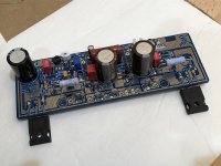
More than work, it shines and sounds spectacular. The installation of the MOSFETs was very easy. Use 5mm standoffs and bend the legs of the IRFP at about halfway down the skinny part and that makes the alignment with the UMS heatsink hole about perfect. You should solder just one leg temporarily to check the fit before committing all three legs to solder. I used four nylon standoffs with built in M3 male screw on one end and female thread on PCB side. I used 10mm M3 hex cap screws and a nickel for a washer to provide the correct spacing to prevent the M3 from bottoming out.
Here is a photo of the installed MOSFETs - note position of edge of MOSFET relative to PCB. You cannot use higher standoffs because the legs of the MOSFET are not long enough to fit the UMS hole and a higher standoff.
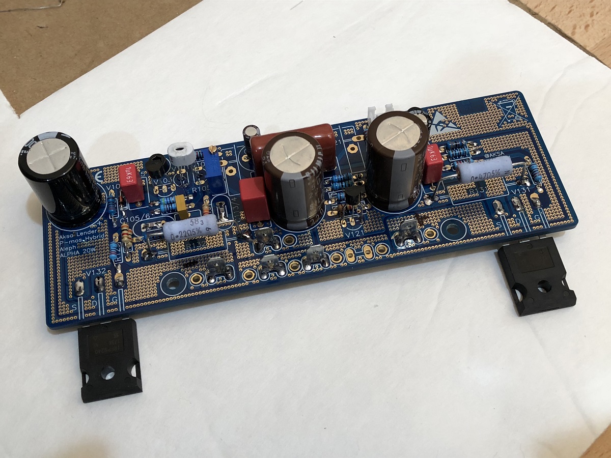
Here is a photo of the PCB installed. It fired up correctly the first time no issues. With 0.47R at R131 and 0.22R at R132 I getr 1.31amps bias current. I matched the Hfe of the KSA992 perfectly and DC offset is 1mV after warmup, and 2mV before warmup. Basically, perfect behavior for the thermally bonded LTP.

I am using a Pass F6 PSU design (all P2P) and this is providing +/-22.5v at load with one channel. At 1.31 amps this is 60w dissipation per side. I do not think I need more bias current because Hugh's design and JPS64's layout provides unbelievable performance.
Here is the FFT for 2.86vrms into 8ohms (source is a Cayin N3 DAP playing a 1kHz test tone generated from Audacity and stored as a lossless FLAC). The N3 has a real nice low distortion AK4990 DAC.
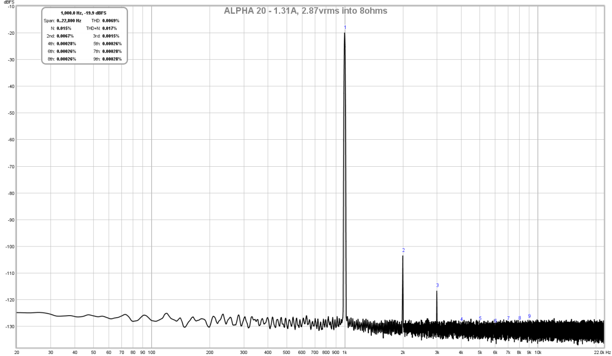
As you can see, the THD is 0.0069% - one of the lowest I have see for a Pass Aleph CCS. My Aleph J comes in at 0.17% THD and my Babelfish J comes in at 0.15% THD - a totally different ballgame (although I purchased a $55 set of matched LSJ74 JFETs, which may be the source of the higher distortion, although on Babelfish J, I am using all genuine JFETs). With the ALPHA, there is no need for exotic expensive JFETS - just some KSA992 at pennies a piece. The harmonic profile is superb, as expected with primarily H2 and H3 lower by about -15dB and no higher orders.
You can see that this amp behaves almost like an Aksa Lender preamp but with ability to drive 8 ohms loads!
I will install the second channel now, but we can all breath easier now knowing that this amp is superb. I am using cheap no-name Chinese resistors except for R131 and R132, which are Panasonic metal thin film 3W. All caps are genuine Silmic II, Nichicon, Panasonic, Wima. I was concerned about C112 needing to be a film cap but I am using a Milspec AVX M390 14/01 1577 (13nF) MLCC there and it seems to work fine. For C105 and C113 I am using 22pF NP0 SMT.
One thing to note is that this is the first amp that I am using with a linear trafo and CRC type PSU that registers no hum on the FFT! It is dead silent. I am not sure why, but it must have to do with Hugh's design, which apparently has a very high PSRR and the layout ground plane and ground topology seems to be doing its job. You could use this amp as a headphone amp and it would be silent.
Here is the FFT at 4.04vrms into 8ohms (2w) - still very well behaved, THD is just under 0.01%:
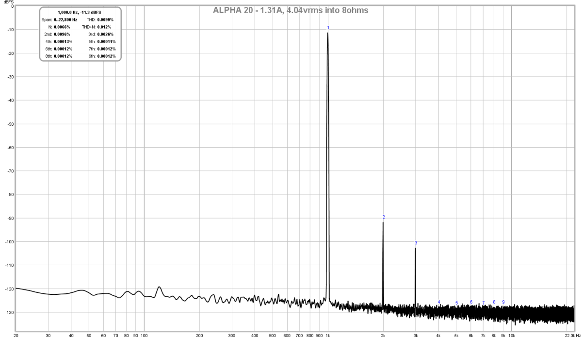
My hats off to Hugh and JPS64 for another exceptional amplifier design and layout!

More than work, it shines and sounds spectacular. The installation of the MOSFETs was very easy. Use 5mm standoffs and bend the legs of the IRFP at about halfway down the skinny part and that makes the alignment with the UMS heatsink hole about perfect. You should solder just one leg temporarily to check the fit before committing all three legs to solder. I used four nylon standoffs with built in M3 male screw on one end and female thread on PCB side. I used 10mm M3 hex cap screws and a nickel for a washer to provide the correct spacing to prevent the M3 from bottoming out.
Here is a photo of the installed MOSFETs - note position of edge of MOSFET relative to PCB. You cannot use higher standoffs because the legs of the MOSFET are not long enough to fit the UMS hole and a higher standoff.
Here is a photo of the PCB installed. It fired up correctly the first time no issues. With 0.47R at R131 and 0.22R at R132 I getr 1.31amps bias current. I matched the Hfe of the KSA992 perfectly and DC offset is 1mV after warmup, and 2mV before warmup. Basically, perfect behavior for the thermally bonded LTP.
I am using a Pass F6 PSU design (all P2P) and this is providing +/-22.5v at load with one channel. At 1.31 amps this is 60w dissipation per side. I do not think I need more bias current because Hugh's design and JPS64's layout provides unbelievable performance.
Here is the FFT for 2.86vrms into 8ohms (source is a Cayin N3 DAP playing a 1kHz test tone generated from Audacity and stored as a lossless FLAC). The N3 has a real nice low distortion AK4990 DAC.
As you can see, the THD is 0.0069% - one of the lowest I have see for a Pass Aleph CCS. My Aleph J comes in at 0.17% THD and my Babelfish J comes in at 0.15% THD - a totally different ballgame (although I purchased a $55 set of matched LSJ74 JFETs, which may be the source of the higher distortion, although on Babelfish J, I am using all genuine JFETs). With the ALPHA, there is no need for exotic expensive JFETS - just some KSA992 at pennies a piece. The harmonic profile is superb, as expected with primarily H2 and H3 lower by about -15dB and no higher orders.
You can see that this amp behaves almost like an Aksa Lender preamp but with ability to drive 8 ohms loads!
I will install the second channel now, but we can all breath easier now knowing that this amp is superb. I am using cheap no-name Chinese resistors except for R131 and R132, which are Panasonic metal thin film 3W. All caps are genuine Silmic II, Nichicon, Panasonic, Wima. I was concerned about C112 needing to be a film cap but I am using a Milspec AVX M390 14/01 1577 (13nF) MLCC there and it seems to work fine. For C105 and C113 I am using 22pF NP0 SMT.
One thing to note is that this is the first amp that I am using with a linear trafo and CRC type PSU that registers no hum on the FFT! It is dead silent. I am not sure why, but it must have to do with Hugh's design, which apparently has a very high PSRR and the layout ground plane and ground topology seems to be doing its job. You could use this amp as a headphone amp and it would be silent.
Here is the FFT at 4.04vrms into 8ohms (2w) - still very well behaved, THD is just under 0.01%:
My hats off to Hugh and JPS64 for another exceptional amplifier design and layout!
Attachments


Last edited:
- Home
- Amplifiers
- Solid State
- Aksa Lender P-MOS Hybrid Aleph (ALPHA) Amplifier