Thanks for your suggestion Mooly, I'll measure those and get back to you.
It's weird. Musically it sounds absolutely fine on both channels, though predictably a little less volume on the right channel, due I suppose to that 17.1V DC balance instead of the normal 28.1V of the left channel. Other than that oddity, there's no audible nasties whatsoever on the right channel. Both sound very good through a pretty revealing set of headphones (Audio-Technica ATH-AD700s). No hum or distortions.
Hoping this means something relatively minor to fix (famous last words!)")
J
It's weird. Musically it sounds absolutely fine on both channels, though predictably a little less volume on the right channel, due I suppose to that 17.1V DC balance instead of the normal 28.1V of the left channel. Other than that oddity, there's no audible nasties whatsoever on the right channel. Both sound very good through a pretty revealing set of headphones (Audio-Technica ATH-AD700s). No hum or distortions.
Hoping this means something relatively minor to fix (famous last words!)
J
Hi.
OK, TR2 on the healthy (Left) channel:
Base: 1.4V
Collector: 27V
Emitter: 0.9V
Pretty much dead on according to the circuit posted below.
TR2b (or not 2b? Sorry couldn't resist!), the Right channel:
Base: 16.3V
Collector: 16.4V
Emitter: 0.4V
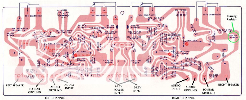
So, does this point to a dicky transistor here Mooly?
J
OK, TR2 on the healthy (Left) channel:
Base: 1.4V
Collector: 27V
Emitter: 0.9V
Pretty much dead on according to the circuit posted below.
TR2b (or not 2b? Sorry couldn't resist!), the Right channel:
Base: 16.3V
Collector: 16.4V
Emitter: 0.4V
So, does this point to a dicky transistor here Mooly?
J
Last edited:
Definitely pancaked with 16 volts across B and E.
Replace the transistor, and I would turn the bias back to minimum before powering up again because it will need resetting and it could be way to high after replacement.
This being the type of issue it is... always expect the unexpected... you just might find other problems once the transistor is replaced.
OK will get a replacement. Are there any modern alternatives you'd suggest for the 2SC945(L) transistor? I've seen KSC1845 mentioned a few times. As the Akai diagram above specifies K or P grade hFE for the 945s I guess any replacement transistor in that position needs to be between 200-600 grade, as long as they're matched between channels?
Suitable for TR2?
http://uk.farnell.com/fairchild-sem...ll+Categories&categoryNameResp=All+Categories
P.S. Handily, it appears that a suitable TR1 (2SC1222) replacement is also the KSC1845 too! I'm thunking of ordering a pack of 25, that was can get appropriate hFE matches to the original items. I'm assuming after replacing TR2 TR1 might also prove to be problematic too, so thinking ahead here
Last edited:
Pretty much anything would work for these two. The KSC1845 looks fine even though it is only a 0.05A device. The old favourite 2N5551 comes to mind too.
Honestly, anything remotely suitable will work 100% for these. There is no advantage trying to match hFE
Thanks Mooly
Well I can easily order either for TR1 & 2 - both readily available from RS & Farnell. Given the choice which would you go for?
I'd feel happier with the 5551 for the power amp, simply because of its much higher current rating. Get some of both, they are all good general purpose devices.
OK so a set of 5551s to replace both the 2SC945 (TR2) & 2SC1222 (TR1) then. I'll order those now (& ignore the hFE matching).
Looks like I'll have to do some leg twisting to match the original NEC pin out holes.
It'll be a fully re-transistorised amp board now - that'll teach me to make silly mistakes in the future!
Touch wood should have it fixed by Tuesday if RS deliver on time
Last edited:
I'll go for the OnSemi brand:
2N5551RLRAG | ON Semi 2N5551RLRAG NPN Bipolar Transistor, 600 mA, 160 V, 3-Pin TO-92 | ON Semiconductor
2N5551RLRAG | ON Semi 2N5551RLRAG NPN Bipolar Transistor, 600 mA, 160 V, 3-Pin TO-92 | ON Semiconductor
Thanks Mooly - yes much cheaper (and what would I do with 96 spare 5551's from RS afterall ).
I'm going to also order a pair of 25-turn 200R trimmers for VR2/2b as well, as the current single turn item is way too 'jumpy' to get a really solid setting of 40mA idling current as dictated in the service manual. Both the original pots, and the replacement Bourns single-turn both exhibited this behaviour, so I think 25-turn will prove useful here. The 30K VR1/1b on the other hand adjust fine with a single turn item (well, before I blew the right channel anyway!).
Novice question alert: The service manual has two adjustments: Idling Current, and DC Balance. Which of those two refer to bias adjustment? Thanks.
).I'm going to also order a pair of 25-turn 200R trimmers for VR2/2b as well, as the current single turn item is way too 'jumpy' to get a really solid setting of 40mA idling current as dictated in the service manual. Both the original pots, and the replacement Bourns single-turn both exhibited this behaviour, so I think 25-turn will prove useful here. The 30K VR1/1b on the other hand adjust fine with a single turn item (well, before I blew the right channel anyway!).
Novice question alert: The service manual has two adjustments: Idling Current, and DC Balance. Which of those two refer to bias adjustment? Thanks.
Idling current is the bias. That's VR2 and it sets the standing or quiescent current in the output transistors. DC balance is the 30k preset and that adjusts the 'midpoint voltage' to be equal to half the supply voltage (so that it can swing equally above and below that voltage for maximum output).
Minimum resistance for VR2 (so effectively shorted out) gives minimum bias current.
Minimum resistance for VR2 (so effectively shorted out) gives minimum bias current.
Idling current is the bias. That's VR2 and it sets the standing or quiescent current in the output transistors. DC balance is the 30k preset and that adjusts the 'midpoint voltage' to be equal to half the supply voltage (so that it can swing equally above and below that voltage for maximum output).
Minimum resistance for VR2 (so effectively shorted out) gives minimum bias current.
Thanks for explaining that Mooly.
Is it normal then for the bias reading to take a while to stabilise? On this amp (before the accident), and on an identical model I recapped for a friend last year, it took a good 5-10mins before the readings stopped fluctuating (mostly rising) enough to set properly. Assume that's tied in with the heatsink temperature & reaching a thermal equilibrium etc?
Its very normal on an amp like that.
Make sure you set it to the correct value when the amp is quite warm. If you play the amp loud so it gets hot, the bias should return to around the correct value within a minute or two. What you want to guard against is 'thermal runaway' where the bias continues to increase... sometimes destructively.
So if it is say 60ma after playing loud and then falls to 20ma as it cools then it is fine. You might not do much better than that with a design like this. Make sure its OK from absolute cold too. Anything over even a couple of milliamps will remove any audible distortion. Always play safe, don't be tempted to increase the bias as designs like this aren't thermally very stable.
Thanks Mooly - appreciate you taking the time to explain that. So set whilst warmed up, then blast out some music for a while. Disconnect speakers & source again & recheck bias. I get the impression it's not an exact science in the real world since ambient temperatures and locations can vary greatly. The top of the chassis is wood covered with 'wood effect' (sort of!) veneer too so I imagine that stores up heat far more than an all metal chassis.
Anyway, thanks again. Awaiting delivery of those tranasistors & the two 30K replacement trimmers now. In the meantime will replace all three bulbs behind the front fascia, which I have spares for. Cosmetically it looks like new otherwise, so fingers crossed I can cross the final hurdle at some point this week & get it sounding like new too
Anyway, thanks again. Awaiting delivery of those tranasistors & the two 30K replacement trimmers now. In the meantime will replace all three bulbs behind the front fascia, which I have spares for. Cosmetically it looks like new otherwise, so fingers crossed I can cross the final hurdle at some point this week & get it sounding like new too
Its not an exact science on a design like this. It could be made better... but not easily. You would need a correctly designed vbe multiplier (using a transistor instead of those diodes) and mounted in direct contact with one of the output transistors (not just the heatsink). Something like that would give much better control and correction and you would be able to get the bias to remain constant from cold through to extremely hot.
Its not an exact science on a design like this. It could be made better... but not easily. You would need a correctly designed vbe multiplier (using a transistor instead of those diodes) and mounted in direct contact with one of the output transistors (not just the heatsink). Something like that would give much better control and correction and you would be able to get the bias to remain constant from cold through to extremely hot.
Sounds like it might be worth looking into once the amp is (touch wood) running well again, once those last two transistors are replaced. If I could install it neatly without it looking like too much of a rats nest of extra components it would seem like a worthwhile modification to get the best out of it.
P.S. There is one slight mod I've made, which I'd be interested to hear your thoughts on Mooly. Obviously this design pre-dates the 80s onwards obsession with minimalism. As such the signal goes through the initial input (which also contains the RIAA & Tuner circuits) pcb, then into the tone control pcb, then into a tiny high/low filter pcb, then into the power amp pcb. I wired directly from the output of the tone control pcb to the amplifier, as I never use the high/low switches (which were noisy anyway), and if need be I can use the tone controls anyway. I wasn't sure if I've now affected the corner frequency though? The output of the tone control pcb is via a 2.2uF coupling cap. The input of the amp pcb is via a 0.47uF cap. Would it be beneficial to replace the 2.2uF on the tone control pcb output with wire links, and increase the amp boards input caps to around 2.2 or 3.3uF perhaps? I'll try and post the full circuit diagram which also shows the mini filter board later on.
- Home
- Amplifiers
- Solid State
- Akai AA-1020 burning resistor woe!