hello everyone, sorry for the broken text, I'm talking through a translator)
Tell me the correct name of the scheme? I own an aa-1020 and a couple more amplifiers, such as the AX-1070 Yamaha, as well as denon pma-235 and a single-cycle, tube amplifier. So, aka during long listening gives me more pleasure, he has excellent depth, width and bass, it is soft) and in my opinion, in some cases, bypasses more expensive and modern brothers. I understand how the push-pull, single-cycle, class a, ab, d ... work, but in this case, single-cycle, unipolar power supply, the end-stage circuit is built only on transistors, npn wire, those. one stroke, but in what class? this is not all, but it’s both small and not all that is needed to see which circuits can be used to search and use amplifiers for listening)
Tell me the correct name of the scheme? I own an aa-1020 and a couple more amplifiers, such as the AX-1070 Yamaha, as well as denon pma-235 and a single-cycle, tube amplifier. So, aka during long listening gives me more pleasure, he has excellent depth, width and bass, it is soft) and in my opinion, in some cases, bypasses more expensive and modern brothers. I understand how the push-pull, single-cycle, class a, ab, d ... work, but in this case, single-cycle, unipolar power supply, the end-stage circuit is built only on transistors, npn wire, those. one stroke, but in what class? this is not all, but it’s both small and not all that is needed to see which circuits can be used to search and use amplifiers for listening)
Attachments
The AA-1020 operates in Class AB but with a very low bias current.
The circuit configuration of it being a simple single ended input stage (not a differential pair) is one of the main reasons it sounds as good as it does... the distortions it produces are inoffensive on the ear.
The Quasi Complementary (using two NPN output transistors) is also another possible reason as these configurations had a reputation for good sonics.
Single or split rail design has no real impact here and it is possible to make amplifiers like this using DC coupling but these would need extra circuitry like a DC servo to keep the DC operating point close to zero.
The technical performance of a simple design like this is not great... but they usually sound excellent")
The circuit configuration of it being a simple single ended input stage (not a differential pair) is one of the main reasons it sounds as good as it does... the distortions it produces are inoffensive on the ear.
The Quasi Complementary (using two NPN output transistors) is also another possible reason as these configurations had a reputation for good sonics.
Single or split rail design has no real impact here and it is possible to make amplifiers like this using DC coupling but these would need extra circuitry like a DC servo to keep the DC operating point close to zero.
The technical performance of a simple design like this is not great... but they usually sound excellent
Attachments
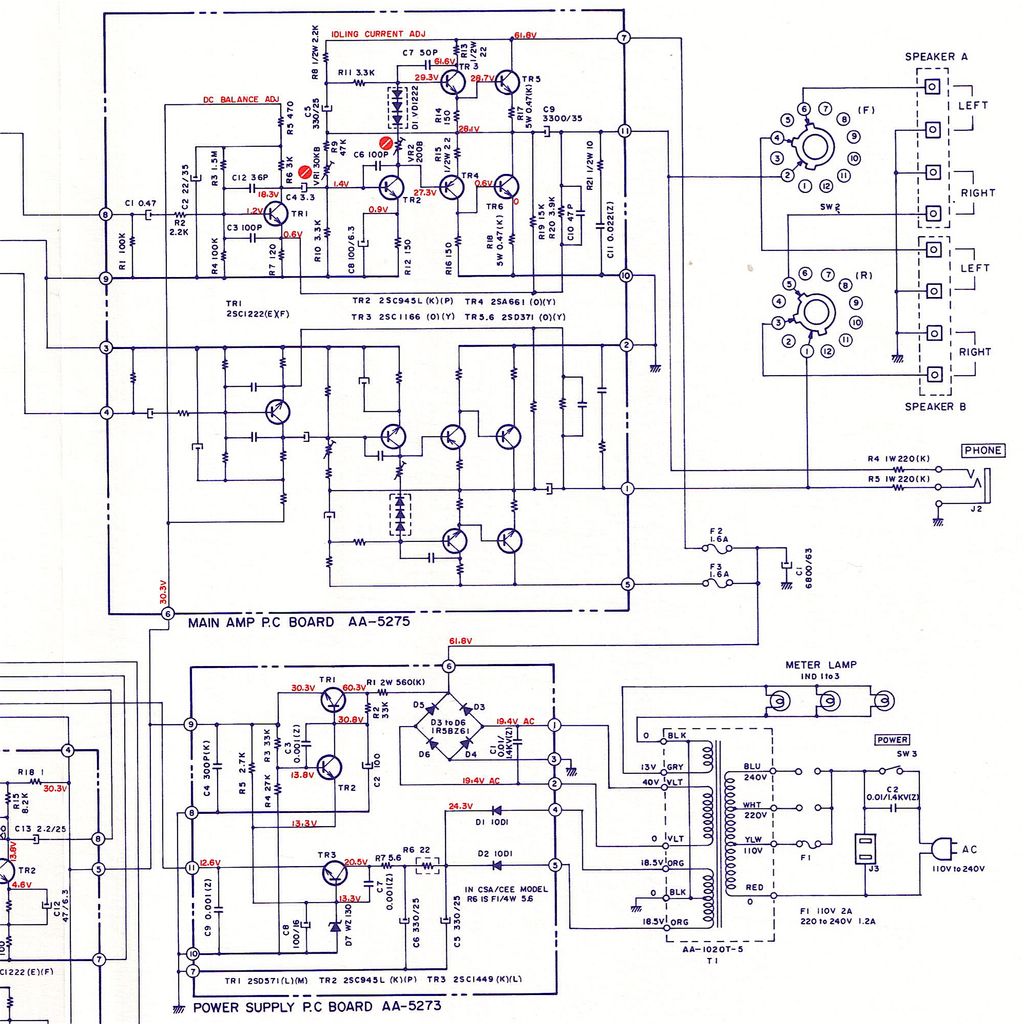
Hi, very old topic, but thanks for all the info shared here! I'm working on an Akai AA-1020 and I think there is a mistake in the amplifier board schematic. TR4b seems wrong. Compare with TR4. E-C-B must be reversed and that could also explain the resistance problem.Hi folks!
Hoping somebody can help me to fix up my Akai AA-1020 which has been (hopefully temporarily) put out of action due to my own stupidity!
The amp had been recapped recently, adjusted, and was working beautifully. Sounded lovely. The only problem was the old headphone socket was cracked and resulted in intermittent connection with the jack inserted. Fortunately I sourced another that was an extremely close match. Did a test fit of the new socket to make sure… and forgot I'd left it there... loose! Yep (slaps forehead!).
Had just turned off the power (thankfully, or it might have been worse) after a listening session, and the socket decided to fall into the internals at that point, creating a spark and there was a loud pop. As I said the power was off, so it was either residual charge left in the reservoir cap, or from touching the live terminals of the on/off switch (probably the most likely). Obviously there must have been some short. The spark was large enough to burn off a corner of one of the solder tags on the new headphone socket as it fell to the chassis base!
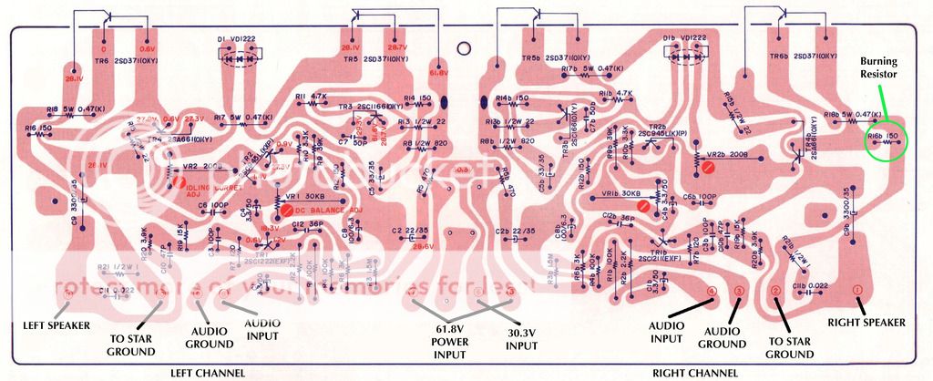
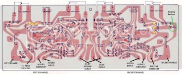
Whenever the amp is turned on now, R16b (150R) starts smoking almost immediately. Replaced it with a new one and the same result, so obviously I've really screwed something up. This is alas out of my league really, so was hoping somebody might be able to look at the circuit diagram's below, and the PCB layout (smoking resistor circled in green) and spot a potential component to check and change. I'm hoping the transistors haven't blown from that short, but sod's law being what it is I'm guessing that's what's happened.
I can’t take any voltage readings on the amp board at the moment as that resistor starts heating up immediately. Have checked for any obvious burn marks on all PCBs (there aren’t) and there’s no sign of any blown components, at least not visually.
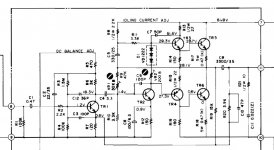
Main PSU and Amp PCB circuit (rest of the circuit not shown is for tone control and RIAA boards):
Amplifier Board:
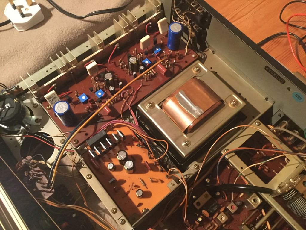
What it looks like for real:
Where to start?
Any help would be very gratefully received
Thanks.
- John
Attachments
Last edited: