IDS25 Advantages of the IDS Technology is a line source done with multiple 3" drivers, clones typically with Some Dayton or TangBand drivers.
Keele's CBT is a developed version of same idea Audio Artistry / CBT Products
Keele's CBT is a developed version of same idea Audio Artistry / CBT Products
When I look at Patricks graph, and normalize that in my mind, vertical Neo8-PDR should do the job very well to 5-6kHz LR4xo, or 4-5kHz LR2. Was there some baffle in that measurement?
What I don't like about line sources is their horizontal dispersion. My friend ahs this wonderful mix of dipole H-rame bass, dipole line soruce and Fountek Neo3 with waveguide. But I can't even think of suggesting something like this in our living room!
What I don't like about line sources is their horizontal dispersion. My friend ahs this wonderful mix of dipole H-rame bass, dipole line soruce and Fountek Neo3 with waveguide. But I can't even think of suggesting something like this in our living room!
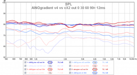
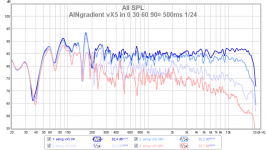
Here are outdoor measurements of HM/T xo LR2@3000Hz (v4, blue) vs LR4@3000Hz (vX2, red)
We can see that the LR2 version has much smoother response at the problematic 2kHz area, where HM driver Peerless NE95 shifts dipole peak to lower fq at large angles. Also transition from dipole to monopole (=cardioid directivity) is slower/wider then.
This means that I'll soon go to vX6 that will has xos like this
- W/LM LR2@150Hz
- LM/HM LR2@800Hz
- HM/T LR2@3000Hz -->indoor directivity measurements tomorrow (it is raining after being a very nice autumn so far)
Attachments
Last edited:
Rudolf, you can of course use my AINO's directivity measurements as an example!
We must remember that these are just 0-90¤ (front area) measurements. A monopole tweeter drops very low 90-180¤ but dipole mirrors the response backwards. This means that when we calculate/think of the total power response they are almost equal. I have not sent you my 0-80 indoor measurements yet, but I will do that soon. I believe that they sound different too.
We must remember that these are just 0-90¤ (front area) measurements. A monopole tweeter drops very low 90-180¤ but dipole mirrors the response backwards. This means that when we calculate/think of the total power response they are almost equal. I have not sent you my 0-80 indoor measurements yet, but I will do that soon. I believe that they sound different too.
This shift is only a visual illusion. The dipole peak keeps its position wrt frequency. A real point-source-dipole would even move its peak to higher frequencies with rising angle.... where HM driver Peerless NE95 shifts dipole peak to lower fq at large angles.
What do we need to consider? We have the case of a large cone on a small baffle - little difference between both sizes. This implies that beaming starts practically immediately at the dipole peak. Beaming starts at the largest angles and moves towards the 0°-axis with rising frequency. On its way it "bites off" SPL from the FR curve - visually speaking.
It is like a stone quarry which starts its business at the east side of a hill, biting off the side of that hill. While the quarry grinds the hill down, the hill's peak moves westward too. This is what we observe. But that does not mean that the hill has moved westward as a whole.
Thank you! It might not surface immediately in my papers, but it will.Rudolf, you can of course use my AINO's directivity measurements as an example!
")
Yes, I thought about that too. At first glance people will say: "Oh no, he can't do that this way". But looking closer we see that your 0-30° response is practically equal for both cases. Differences only start to show from 45° upward. So direct response is almost unaffected. Which means, that everything else will be highly determined by the room reflection and absorption properties. Only a large gate (>20 ms) would tell us if there is any difference left to speak of.We must remember that these are just 0-90¤ (front area) measurements. A monopole tweeter drops very low 90-180¤ but dipole mirrors the response backwards. This means that when we calculate/think of the total power response they are almost equal.
Rudolf
Yes, total power response can be imitated with a long gate measurement in a room.
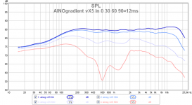
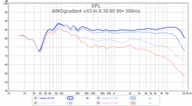
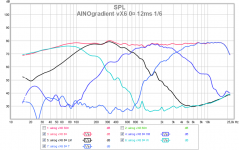
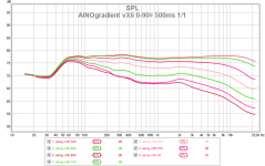
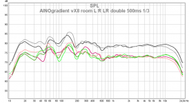
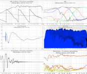
Here an example. Same measerement with the speaker on a stand in the middle of the room (much less reflections than at normal listening placement). IR gate 12ms represents direct radiation and 500ms power response. Mic distance only 80cm here.
It is very common to give too much value to direct response. Lateral response and total room response with all reflections are very very important, if we want to know how the speaker works in real life! This is the reason why many speakers with straight on-axis sound bad and vice versa. A 500ms gate is very close to what we hear and it is so easy to measure, I value it very much as a single measurement.
Attachments
Last edited:
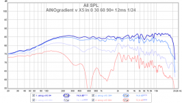
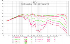
The same measurements with 1/24 smoothing, to see reflections better. I believe that a dipole tweeter would show more reflections, especially close to the windows at my normal listening placement.
From these pic we can clearly see how the room's Schröder effect works below 200Hz! at 12ms gate we notice directivity at 50-200Hz (cardioid response range) but it is lost at 500ms gate.
From these pic we can clearly see how the room's Schröder effect works below 200Hz! at 12ms gate we notice directivity at 50-200Hz (cardioid response range) but it is lost at 500ms gate.
Attachments
Last edited:
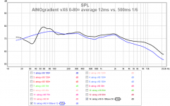
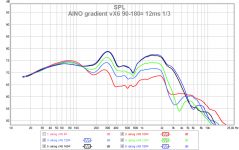
Here are AINOgradient vX6 measurements
We get room/floor reflections up to 300Hz, ignore them. HM/T xo is now LR2 at 3300Hz roughly. The 2kHz peak of NE95's far off-axis response is dominant, otherwise directivity is better than vX5. The 0-180¤ "power response takes only horizontal response in account. The vertical response dips in 2-3kHz region to compensate that. By short listening it sounds just right, perhaps a little more "polite" than LR4 for highest xo. No room measurements today.
We get room/floor reflections up to 300Hz, ignore them. HM/T xo is now LR2 at 3300Hz roughly. The 2kHz peak of NE95's far off-axis response is dominant, otherwise directivity is better than vX5. The 0-180¤ "power response takes only horizontal response in account. The vertical response dips in 2-3kHz region to compensate that. By short listening it sounds just right, perhaps a little more "polite" than LR4 for highest xo. No room measurements today.
Attachments
Last edited:
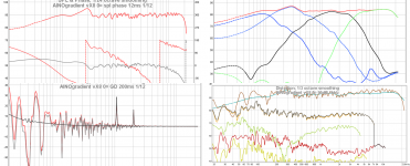
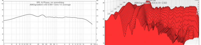
AINOgradient vX8 indoor measurements
I went back to LR4 and higher frequency for highest xo. This way I get a little better overall directivity and room response. The loss of directivity around 2kHz and 600Hz are real, all lower Fq irregularities come from room response.
I show also some impulse responses, not seen earlier. Indoor measurements at 1.3m
Room farfield responses again with the microphone centered well. No room EQ at all.
Attachments
Last edited:
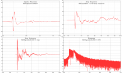
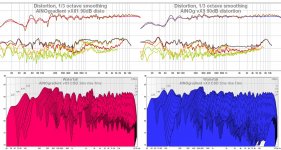
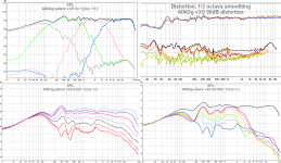
Interesting difference in distortion and decay
I ran a series of distortion checks and I got the idea to change LM to HM crossover from LR2 to LR4. Running just one driver at a time I noticed serius distortion in the low end and also some high end noise obviously passing thru minidsp "slopes"
LR4 xo gives 6dB lower distortion in these measurements between 800-8kHz, mainly due to 3rd harmonic (orange). 2nd (red) and higher are not so strongly attenuated. I think that I have read something about the nature of this 3rd harmonic, but I hope that someone tells an explanation for this.
Nothing was physically changed between these measurements, only minidsp configuration was switched. Measured indoors at 1,2m distance, 90dB measured with UMIK-1 and REW. Now for a few days I don't have time to run ARTA or Holmipulse for distortion.
Attachments
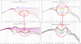
I quickly took directivity measurements of vX9 with LR4 in middle xo.
Seems like fundamentally better results widely off-axis and backwards. These support the previous post showing distortion and csd difference. Obviously LR2 in the middle makes phases messed too much. Perhaps Rudolf can tell us what is really happening here.
I believe that this has nothing to do with HM being double (MTM), because these result are in par with my prototype measurements and distortion measurements with only one section playing at a time.
Attachments
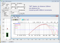
I made a series of Edge simulations to look at MTM vertical lobing. The higher xo means that vertical off-axis has dip at 2-3kHz.
In these simulations the virtual microphone is at 2m, then 30cm (1') elevation means roughly 10¤. Simulation shows response with 10, 20 and 30cm elevation. The sims handle each driver as a fullrange, without xo.
The dip in vertical response however compensates the blooming in the same area when measured horizontally, resulting in smooth power response.
I have ordered Audax HM100Z0 mid drivers but I haven't got them yet. I will make a proto frame and measure responses and distortion later on.
Attachments

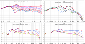
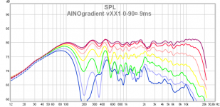
AINOgradient vX91 indoor measurements
A series of indoor measurements, all xos are now LR4 and farfield response was adjusted to be slightly declining towards high frequencies. LR2 versions appeared to have high 3rd harmonic distortion and poor response at lafge angles and backwads, obviously due to phase mismatc. However frontside measurements of LR2 sysm was just fine, excetp CSD and distortion at high level.
Based on this I recommend LR4 crossovers for everyone making multiway dipoles! LR2 is supposed to give smooth transition but here phase behaviour is more important.
90-180¤ measurement show the cardioid response between 50-150Hz, dipole response 150-3000Hz. Peaks at 600Hz and 2000Hz at large angles are caused by "dipole blooming" at dipole peak frequency, which goes lower in Fq laterally.
Room response is very even, measured at 205cm, speakers at normal listening position 60cm from front wall, 45¤ to it.
Attachments
With my latest versions of xo I have gone back to higher xo for HM to T. This has again made the 2kHz "blooming" phenomenom more prominent. I was reading S Linkwitz's pages again and I noticed that he has encountered just same before! Go to section D at this page to see the text of it. I think that this has something to do with the speaker being a cone (not point source nor planar as by modelling simulations)
My 4" HM driver has cone diameter 75mm and has blooming at 2kHz, the 12" LM driver has cone d=260mm and blooming at 4-600Hz.
I will email SL and ask what he thinks of this!
My 4" HM driver has cone diameter 75mm and has blooming at 2kHz, the 12" LM driver has cone d=260mm and blooming at 4-600Hz.
I will email SL and ask what he thinks of this!
Attachments
Last edited:
Go to Electro-acoustic models and look at diagrams A 3-5. Those are simulations of a flat circular piston in a circular baffle, which exhibit the same blooming - if your baffle is too large and/or if you extend your range too much above the dipole peak. Bloom is heaviest at the onset of the dipole notch.With my latest versions of xo I have gone back to higher xo for HM to T. This has again made the 2kHz "blooming" phenomenom more prominent. I was reading S Linkwitz's pages again and I noticed that he has encountered just same before! Go to section D at this page to see the text of it. I think that this has something to do with the speaker being a cone (not point source nor planar as by modelling simulations)
Rudolf,
my 12" nudie has this blooming at 5-600, dipole null at 1300Hz
my 4" nudie has this blooming at 2kHz, dipole null at 4kHz
The behaviour is similar to dipole null blooming, yes. 'These appear below the dipole peak!
Ad Hoc! at null lambda/2!
my 12" nudie has this blooming at 5-600, dipole null at 1300Hz
my 4" nudie has this blooming at 2kHz, dipole null at 4kHz
The behaviour is similar to dipole null blooming, yes. 'These appear below the dipole peak!
Ad Hoc! at null lambda/2!
Attachments
Last edited:
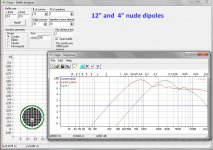
To help seeing dipole behaviour, here are Edge simulations, like above
In an earlier post Rudolf stated that in a frame with some depth, a nude driver has a virtually larger baffle. However I don't believe it can shift from 5 to 2kHz with 8mm plywood + 4mm aluminium frame thickness. The cone is 16mm deep.
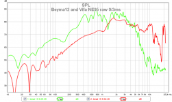
In post #299 Patrick showed Neo8 measured at 0 and 45¤, it doesn't show any this kind of behviour at null/2
In an earlier post Rudolf stated that in a frame with some depth, a nude driver has a virtually larger baffle. However I don't believe it can shift from 5 to 2kHz with 8mm plywood + 4mm aluminium frame thickness. The cone is 16mm deep.
In post #299 Patrick showed Neo8 measured at 0 and 45¤, it doesn't show any this kind of behviour at null/2
Attachments
Last edited:
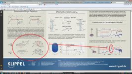
And I remind you of this Klippel poster that I have linked earlier too! http://www.klippel.de/fileadmin/kli...ure/Papers/KLIPPEL_Sound_Radiation_Poster.pdf
Problem similarities highlighted here!
Ref. "Sometimes I feel like a motherless child..."
Problem similarities highlighted here!
Ref. "Sometimes I feel like a motherless child..."
Attachments
Last edited:
Sorry Juhazi,Rudolf,
my 12" nudie has this blooming at 5-600, dipole null at 1300Hz
my 4" nudie has this blooming at 2kHz, dipole null at 4kHz
now I have lost you completely.
There are so many diagrams of yours - where are the ones that show what you state above?
And I'm afraid, I can't discuss any bending cone behaviour. I have no experience with it and only the most basic knowledge.
Rudolf
Sorry but these things are always so clear to the one doing the basic hard work...
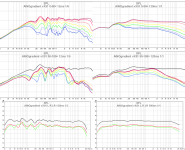
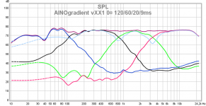
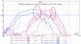
Here is an overlay of 12" LM and 4" HM driver in AINO speaker frame. 20ms gating 1/6 oct smoothing , 0¤ 60¤ and 90¤ sweep of individual drivers with their eq and crossovers activated. I made circles around the problematic areas. They can be spotted also in fullrange measurements.
Here we must remember that the dipole characteristic response is first equalized and then crossovers activated, then slopes were eq'd even more to make slopes "nice" at 0¤ on-axis measurements (or 15¤ actually!)
Circular cone acoustic mathematics/geometrics is way beyond my skills too! That's why I am asking for help!
ps. I just ordered 2 Neo8-PDRs from here! http://www.ebay.com/itm/Bohlender-Graebener-Neo8-PDR-Planar-Transducer-/370881018589?pt=US_Speaker_Parts_Components&hash=item565a3b3add At least I want to see and measure them myself or I can't sleep anymore!
Attachments
Last edited:
- Home
- Loudspeakers
- Multi-Way
- Aino gradient - a collaborative speaker project