Matt a while back do I remember correctly you saying that you were going to mount your regulator upside down?
That would change the pinout of the regulator and could be causing your problem.
man, I did wonder about the holes/solder pads for two reg, one on each side of the heatsink
now I know

man, I did wonder about the holes/solder pads for two reg, one on each side of the heatsink
now I know
Yeah, I was checking that out.... not sure if I want to mount the heatsink on top or bottom myself. Does the voltage reg generate much heat? I have a 12V filament trafo with center tap, so using center tap configuration w 2 diodes.
Just got my package from partsconnexion, going to start on populating the PCB tonight...
The higher the voltage in/out differential the hotter the heatsink will get.
If you have 17V in and 6.3V out you would be best mounting it on top.
If you have 17V in and 12.6V out you should be ok with underneath.
After hours my 17V in 12.6V out gets warm to the touch, top mounted.
If you have 17V in and 6.3V out you would be best mounting it on top.
If you have 17V in and 12.6V out you should be ok with underneath.
After hours my 17V in 12.6V out gets warm to the touch, top mounted.
I went with the 2.5" sink, it's right above vent holes in the chassis and there's plenty of air around it, should be OK. 12.6v out too.
Just ticked that now I have to wait for parts. Again.
I'm really stumped on this though. It's certainly behaving like it's a bad regulator. Any time I get the variac up to 70 the the amp flickers, the dial on the variac jumps between 0 to 70. Anything above that and there's no power at all.
Just ticked that now I have to wait for parts. Again.
I'm really stumped on this though. It's certainly behaving like it's a bad regulator. Any time I get the variac up to 70 the the amp flickers, the dial on the variac jumps between 0 to 70. Anything above that and there's no power at all.
Can you take a pic of the board in its current state?
Sounding initially like maybe:
1. cold solder joint
2. flux making a short somewhere
3. mixup in the wiring for the heaters - for example board configured for CT but you have no CT...
4. Maybe a bad rectifier/diode
5. Maybe 10,000uF caps in wrong orientation
Sounding initially like maybe:
1. cold solder joint
2. flux making a short somewhere
3. mixup in the wiring for the heaters - for example board configured for CT but you have no CT...
4. Maybe a bad rectifier/diode
5. Maybe 10,000uF caps in wrong orientation
I was going through Einric's thread, I think I was attaching the heater supply at the wrong point. I was soldering them to the pads on the edge of the board, but it looks like for full wave I'd want to use the H+/H- pads in the center of the board. Correct?
I have to wait for the new regulator to arrive in any case. I looked very carefully for cold solders with my magnifying visor and didn't see any, also the 10,000uF caps are correct. Those were the first things I checked.
I have to wait for the new regulator to arrive in any case. I looked very carefully for cold solders with my magnifying visor and didn't see any, also the 10,000uF caps are correct. Those were the first things I checked.
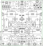
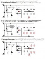
Does your board look exactly like this?
There might be a couple versions out there...this one attached only has one 10,000uF heater supply cap, not 2. Some of the later boards have an updated heater supply circuit with more filtering.
Either way if you are using a Full Wave bridge, you would use all 4 diodes and bypass caps and your heater input wiring would go to the pads at the edge of the board called heater AC. NOT H+/H- Broskie mentions in the Tetra Sans PS post that he added some of these extra heater and B+ taps on the board for some of these new boards that dont have an onboard PSU.
R17 and R18 set the heater reference to B+/4.
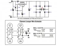
Also, make sure the 1n4007's are in the correct orientation - specifically D1 and D2. I would also check the values of C14 and C15. 1000uF 10V.
There might be a couple versions out there...this one attached only has one 10,000uF heater supply cap, not 2. Some of the later boards have an updated heater supply circuit with more filtering.
Either way if you are using a Full Wave bridge, you would use all 4 diodes and bypass caps and your heater input wiring would go to the pads at the edge of the board called heater AC. NOT H+/H- Broskie mentions in the Tetra Sans PS post that he added some of these extra heater and B+ taps on the board for some of these new boards that dont have an onboard PSU.
R17 and R18 set the heater reference to B+/4.
Also, make sure the 1n4007's are in the correct orientation - specifically D1 and D2. I would also check the values of C14 and C15. 1000uF 10V.
Attachments
Last edited:
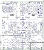
It's the bottom one. Wow, major changes and they both say rev 12b. Here is Einric's post about it, which is where I figured it would be the center pads. Backup a couple posts from here to see how he had it setup, with very similar issues as I have.
http://www.diyaudio.com/forums/tubes-valves/202952-my-first-tube-preamp-14.html#post2863589
http://www.diyaudio.com/forums/tubes-valves/202952-my-first-tube-preamp-14.html#post2863589
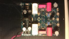
is your HV not hooked up yet?
What tubes are you using? Your heater jumpers are set to series wiring, for 12.6V heater voltage.
Are you shooting for 12.6V heater voltage or 6.3? You should have the 1.13K resistor setting the regulator to 12.6V and I do not see color bands of brown, brown, orange there.
Doublecheck you have 124 ohm at R20 and the correct resistor for what voltage you desire at R21.
Last edited:
I'm wondering about C17. There are three solder pads. I'm assuming I solder C17 to the two outside pads?
wonder and assuming is not very good at the finish line
but if you follow the copper lines and look at schematic, it might help you
- Status
- This old topic is closed. If you want to reopen this topic, contact a moderator using the "Report Post" button.
- Home
- Amplifiers
- Tubes / Valves
- Aikido 9 pin All in One Build