OK, let's hope we can sort this out w/o acrimony. I seem to have way overexplained everything until the main points got lost. And yet I have to do it again.
1) The missing off axis data of post 69.
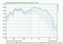
Two days ago I built 2 more test baffles and measured them. One was a larger, 12" muffler, by popular demand. Another was the smaller 9" muffler but with a short tube simulating an U-Tube (sic) baffle. But I made the mistake to fire my off axis into a wall that was too close, and got too much reflections. So the off axis data were usable only with gating. But in all my graphs before I had shown ungated curves to preserve detail and I want things to remain comparable. So I compared what was indeed comparable, which is the ungated curves, which forced me to restrict myself to narrowly on axis responses, in post 69. The first two data sets of that plot btw have previously appeared in full 0 to 90 degree and even sonogram / polar plot incarnations. So, 360 degree hi res data on the first two curves have been shown before, and for the last two curves, don't exist yet.
Why do I prefer to show the measurements ungated? Because, next controversy:
2) John's plot and the missing knee.
I referenced the existence of a knee, or shelf, or resonance, or bump, in my post 16 . In that post, I further reference to a page by Siegfried Linkwitz where SL describes this phenomenon. He explains it as a result of the lowpass behavior of the back of the driver on any dipole baffle, leading to aberrant rolloff behavior in practice, as opposed to theory. I am not sure if he's right on the cause, but over the years, I have seen this bump in all my dipoles so I wasn't surprised, and it also shows up in all of Linkwitz's raw measurements. He EQ's it out, typically with a notch filter of Q around 3 and amplitude -4 to -6 dB, also my experience.
Since our muffler has some kind of radiation coming out the rear, some practical dipole effects have to be anticipated even in the cardioid experiments, and my data show the knee as well. Now why no knee in John's plot? I actually don't know, maybe his device does not exhibit this effect. But the plot shown by John in post 71 is not capable to exhibit any such bump. Reason: it is gated. From the cutoff shown in the graphs, gating is likely around 3 ms. This leads to a frequency resolution of worse than 300 Hz, in other words, it is the same as if you did a full octave averaging in the 300-600 Hz region that interests us. And this would surely melt the knee. Case in point, if I treat my own data, *with* knee, first set of lines in that famous post 69 image , the same way as John's representation in his post 71 , then we clearly see that even in my data the knee has gone.
In addition to this, and to my own surprise, when I took my same 9" muffler data using the appropriate off axis angles, and plot it using John's gating, and rescale and stretch it so the scales match exactly the ones of post 71, then I find that my own data overlap John's post 71 data, almost to perfection, except 135 degree curve, and none have that knee. This I show in the picture of my post 76 . So John when you say in your post 80,
I'd haste to add that John's rear data suggest a better cardioid than mine in the low f's, then again I want to mate it with a dipole at LF so I'm ok with that polar pattern.
Hence: Gating => grain of salt
Sorry for the confusion.
1) The missing off axis data of post 69.
Two days ago I built 2 more test baffles and measured them. One was a larger, 12" muffler, by popular demand. Another was the smaller 9" muffler but with a short tube simulating an U-Tube (sic) baffle. But I made the mistake to fire my off axis into a wall that was too close, and got too much reflections. So the off axis data were usable only with gating. But in all my graphs before I had shown ungated curves to preserve detail and I want things to remain comparable. So I compared what was indeed comparable, which is the ungated curves, which forced me to restrict myself to narrowly on axis responses, in post 69. The first two data sets of that plot btw have previously appeared in full 0 to 90 degree and even sonogram / polar plot incarnations. So, 360 degree hi res data on the first two curves have been shown before, and for the last two curves, don't exist yet.
Why do I prefer to show the measurements ungated? Because, next controversy:
2) John's plot and the missing knee.
I referenced the existence of a knee, or shelf, or resonance, or bump, in my post 16 . In that post, I further reference to a page by Siegfried Linkwitz where SL describes this phenomenon. He explains it as a result of the lowpass behavior of the back of the driver on any dipole baffle, leading to aberrant rolloff behavior in practice, as opposed to theory. I am not sure if he's right on the cause, but over the years, I have seen this bump in all my dipoles so I wasn't surprised, and it also shows up in all of Linkwitz's raw measurements. He EQ's it out, typically with a notch filter of Q around 3 and amplitude -4 to -6 dB, also my experience.
Since our muffler has some kind of radiation coming out the rear, some practical dipole effects have to be anticipated even in the cardioid experiments, and my data show the knee as well. Now why no knee in John's plot? I actually don't know, maybe his device does not exhibit this effect. But the plot shown by John in post 71 is not capable to exhibit any such bump. Reason: it is gated. From the cutoff shown in the graphs, gating is likely around 3 ms. This leads to a frequency resolution of worse than 300 Hz, in other words, it is the same as if you did a full octave averaging in the 300-600 Hz region that interests us. And this would surely melt the knee. Case in point, if I treat my own data, *with* knee, first set of lines in that famous post 69 image , the same way as John's representation in his post 71 , then we clearly see that even in my data the knee has gone.
In addition to this, and to my own surprise, when I took my same 9" muffler data using the appropriate off axis angles, and plot it using John's gating, and rescale and stretch it so the scales match exactly the ones of post 71, then I find that my own data overlap John's post 71 data, almost to perfection, except 135 degree curve, and none have that knee. This I show in the picture of my post 76 . So John when you say in your post 80,
, my overlay in post 76 shows that I see just what John sees, once I use 3 ms gating."I would expect to see the response (below about 1k Hz) look more like this (which is what I see in my case)"
I'd haste to add that John's rear data suggest a better cardioid than mine in the low f's, then again I want to mate it with a dipole at LF so I'm ok with that polar pattern.
Hence: Gating => grain of salt
Sorry for the confusion.
I believe you are misinterpreting SL's comments. The bump he is talking about is due to in phase summation of the front and rear response. Its magnitude will depend on how symmetric the front and rear radiation is and how directional the driver is at the frequency in question. The frequency of this bump theoretically occurs where the wave length is twice the effective front to rear delay. There is no shelf in SL's data.
If the rear response is LP filtered with corner frequency much lower than the bump frequency the bump becomes effectively that which you would see for a sealed with similar sized baffle.
The shelf in you data may be a result of the muffler acting as a low pass filter with corner point probably below 400 Hz. Thus, above 400 Hz the system is basically acting as a sealed box with little radiation form the rear escaping and summing to the front. Below 400 Hz you have cancellation from the rear.
But that the response at much lower frequency starts to look more like a figure 8 is an indication that the muffler does not introduce sufficient delay to form a cardioid. To me, this seems at odds with what the apparent corner frequency if the LP filter would need to be.
It's really difficult to tell through Internet conversation.")
If the rear response is LP filtered with corner frequency much lower than the bump frequency the bump becomes effectively that which you would see for a sealed with similar sized baffle.
The shelf in you data may be a result of the muffler acting as a low pass filter with corner point probably below 400 Hz. Thus, above 400 Hz the system is basically acting as a sealed box with little radiation form the rear escaping and summing to the front. Below 400 Hz you have cancellation from the rear.
But that the response at much lower frequency starts to look more like a figure 8 is an indication that the muffler does not introduce sufficient delay to form a cardioid. To me, this seems at odds with what the apparent corner frequency if the LP filter would need to be.
It's really difficult to tell through Internet conversation.
soongsc said:It would be a good idea to look at impedance of the setup compared with free air.
yep!
john k... said:I believe you are misinterpreting SL's comments. The bump he is talking about is due to in phase summation of the front and rear response. Its magnitude will depend on how symmetric the front and rear radiation is and how directional the driver is at the frequency in question. The frequency of this bump theoretically occurs where the wave length is twice the effective front to rear delay. There is no shelf in SL's data.
The quote I am referring to reads: "Very important to note is the first response peak. It is a function of the driver used and almost all drivers exhibit it to varying degrees. The peak is caused by an acoustic filter formed by the basket openings and trapped air between cone and basket. This filter is the reason for the differences in high frequency response between front and rear." Above this quote on SL's page is a graph of a circular baffle's FR with a bump like thing (the double arrow in the graph points to it). After the quote is the FR of the Phoenix baffle showing a shelf like thing.
The shelf in you data may be a result of the muffler acting as a low pass filter with corner point probably below 400 Hz. Thus, above 400 Hz the system is basically acting as a sealed box with little radiation form the rear escaping and summing to the front.
Leaving aside possible reasons for a while: does my overlay plot of post 76 not shows that my 9" muffler is acting exactly like your device of post 71? Do my 9" muffler's curves for 0, 45, and 90 degrees not follow your device's curves very closely in the overlay?
The complete 0-90 degree ungated polars of my same 9" muffler here. Now compare to the same muffler but with closed sides and just small rear openings, like a transmission line type box (but a short one), in the attached file. Leave aside the undesirable lumpiness introduced, and look at the radiation patterns: are they the same?
Attachments
MBK said:
I referenced the existence of a knee, or shelf, or resonance, or bump, in my post 16 . In that post, I further reference to a page by Siegfried Linkwitz where SL describes this phenomenon. He explains it as a result of the lowpass behavior of the back of the driver on any dipole baffle, leading to aberrant rolloff behavior in practice, as opposed to theory. I am not sure if he's right on the cause, but over the years, I have seen this bump in all my dipoles so I wasn't surprised, and it also shows up in all of Linkwitz's raw measurements. He EQ's it out, typically with a notch filter of Q around 3 and amplitude -4 to -6 dB, also my experience.
OK, I get it. When I visited the Linkwitz room at the last RMAF show, I looked at the builder's manual for the Orion. I was particularly interested in the shape of the EQ curves for the bass and midrange - as expected, the tweeter had a conventional 24 dB/octave highpass filter, since it effectively operates in a half-space.
The mid EQ curve looked like a lopsided "M", with the lower-frequency peak of the "M" about 3 dB higher than the upper peak of the "M", and the dip between two peaks about 6~8 dB or so. This would be phenomenally inefficient to realize as a passive crossover, and the shape of the curve made it clear why the system must use active equalization. The bass curve, even more so, with what looked like 15~20 dB of bass lift starting at 250 Hz going down to 22~25 Hz, and then dropping like a rock below that. Very heavy equalization by any standard - but the whole system sounded good and beautifully balanced, so it was hard to argue with the results. Based on those curves and the moderate efficiency of the Scan-Speak drivers, it requires powerful amplifiers for the mid and bass - no triode amps need apply.
Now, this is all from memory, so the amounts of equalization and the turnover frequencies are probably not spot-on. But these were the general shapes I saw in the builder's handbook. Since I'm not going down the Linkwitz path of op-amp equalization and high-powered Class AB transistor amps, I have to seek other solutions.
Here's a link to somebody else's adventures in cardioid. It's in Finnish, but the photos of the concepts and the measurements are interesting nonetheless:
http://kotisivu.dnainternet.net/anukaa/
Click "Kardioidibassot" on the left side menu.
http://kotisivu.dnainternet.net/anukaa/
Click "Kardioidibassot" on the left side menu.
Markus,
Ok, given that there is a basket resonance. But SL's comments and explanation do not tell the hold story. I'll address this in more detail tomorrow with some measurements of SL's set up (SS 8554 on a 16" circular baffle). The resonance isn't really the issue. It's there box, OB or cardioid.
But this still doesn't explain the shelf and sudden change of slope of the roll off you see around 400 Hz. Notice that SL's response does not show that effect.
Lynn,
Typical dipole midrange eq is a Q notch to correct for the +6dB bump (and any other effects) in the response where the front and rear response sum in phase and a pole shifting filter to flatten the response below the peak. Baffle size is also important. As I have said many times the baffle must be small enough so that the frequency where the first dipole null would appear is well above the frequency where the driver become directional. Thus, no radiation (or only slight) wraps around from the rear and there is no null as a result. A lot of OB builder use large baffle to extend the low frequency response of the mid but this is a mistake.
Lynn,
no question SL uses heavy EQ. Part of my experimenting is to find out if one can lessen the number of filters or get by without them. The other part is to make construction as non exotic as possible.
Hennie,
intersting link! Someone went all the way there...
John,
I agree one should either make the baffle vary large, or very small, w.r.t. driver diameter. Anything in the middle will produce lots of active filters in the process.
Here we see the same data differently. What I see is this: a bump whatever the cause, in SL's various models, and in my various iterations. These bumps look different depending on driver and baffle, but they're always there. And these bumps cause an artificial extension towards the bass, of the first dipole peak, which I would like to avoid. The peak then causes a dipole falloff that is initially faster than the expected 6 dB/oct. (when the system comes 'off' thew peak).
In my 9" baffle btw. the bump is hardly there at all, and to repeat for the umpteenth time, if my muffler has it then so has yours, because our curves look identical (within reason).
no question SL uses heavy EQ. Part of my experimenting is to find out if one can lessen the number of filters or get by without them. The other part is to make construction as non exotic as possible.
Hennie,
intersting link! Someone went all the way there...
John,
I agree one should either make the baffle vary large, or very small, w.r.t. driver diameter. Anything in the middle will produce lots of active filters in the process.
But this still doesn't explain the shelf and sudden change of slope of the roll off you see around 400 Hz. Notice that SL's response does not show that effect.
Here we see the same data differently. What I see is this: a bump whatever the cause, in SL's various models, and in my various iterations. These bumps look different depending on driver and baffle, but they're always there. And these bumps cause an artificial extension towards the bass, of the first dipole peak, which I would like to avoid. The peak then causes a dipole falloff that is initially faster than the expected 6 dB/oct. (when the system comes 'off' thew peak).
In my 9" baffle btw. the bump is hardly there at all, and to repeat for the umpteenth time, if my muffler has it then so has yours, because our curves look identical (within reason).
MBK said:John,
I don't know what to tell you because the off axis data you are talking about, that one would have to see, I already provided them 0-90 degrees forward in all but my last plot, for something like 5 or 6 different setups, and they all look different. That's a good dozen of detailed forward FR families in 7.5 degree intervals, too many to quote in links. In post 67 I explain why this last batch I can't show all off axis angles. Then, I also showed 360 degree full frequency sonograms in post 11, in post 17 and post 18. 360 degree polars? see post 13 . You asked for lower frequency full polars? I didn't replot but explained qualitatively what happes, in post 47 which also has a plot to address measured low pass effect of my muffler.
In your post 71 you also have a substantial falloff, if I extrapolate a little total falloff rom the 1000+ Hz peak down to 300 Hz, easily 10 dB, like me. No "shelf" though, and your 135 degree data look much more cardioid than mine, though your data is really very limited. As I explained in the posts cited above, mine progressively reverts to quasi dipole below 500-600 Hz and as I said in my case this may be a good thing, dipole waiting below for X-O at 300 Hz.
And to make this complete, here is a graph drawn exactly to the model of your post 71 . This is my 9" muffler, no baffle, at 0, 45, 90 and 135 degrees, tried to window it similarly to your pic, same frequency ranges and all. At lower frequencies my lines somehow get closer and the 135 line is clearly showing a come back of the rear lobe (attenuated figure eight), else though I don't see much of a difference.
You know Markus, they are what they are. If I measured to low frequency, as I do for design work, you would see my response continue to roll off smoothly and pretty much be the 6dB/oct "dipole roll off" superimposed on the driver's given Fs, Qts response. Perhaps the shelf, or corner at 400 hz in your cases is more an indication of some type of enclosure resonance, or the effect of the enclosure loading the back side of the driver. That was my initial impression. Looking at you pictures I do know that we construct our mufflers differently and mine are not prone to allowing internal resonances. In any event, I don't think we can resolve this over the Inet.
I'll discuss the dipole bump and the basket resonance later as I have to run out now. But I don't think thatis the issue here. It' something else.
Lynn Olson said:
The mid EQ curve looked like a lopsided "M", with the lower-frequency peak of the "M" about 3 dB higher than the upper peak of the "M", and the dip between two peaks about 6~8 dB or so. This would be phenomenally inefficient to realize as a passive crossover, and the shape of the curve made it clear why the system must use active equalization. The bass curve, even more so, with what looked like 15~20 dB of bass lift starting at 250 Hz going down to 22~25 Hz, and then dropping like a rock below that. Very heavy equalization by any standard - but the whole system sounded good and beautifully balanced, so it was hard to argue with the results. Based on those curves and the moderate efficiency of the Scan-Speak drivers, it requires powerful amplifiers for the mid and bass - no triode amps need apply.
Now, this is all from memory, so the amounts of equalization and the turnover frequencies are probably not spot-on.
It's OK John, I really did not intend this thread to sink into a quagmire of conjectures and refutations, like so many other threads. We don't have to go there. People interpret the same data differently and this is not unusual.
With this thread I really just wanted to throw out as many good data as possible on a narrow subject, as fast as possible and with little personal interpretation before things would get out of hand. Sort of like a scientific paper that tells a specific story, with supporting data, for the benefit of all.
There are precious little data on the forums, and lots of speculations and what ifs, and while discussion is good, and I learned a lot over forums, good hard data are better. So I wanted to contribute something useful and real, warts and all, free to interpret as anyone likes. Then I got tempted to interpret my data rather than just showing them and this is where the yes-it-is no-it-ain't stories began.
In any case I plan to build more devices to answer my own questions, and to get to a reasonable result for my purposes. I'll be posting those data on an as-is basis once there's enough of them to answer specific questions with specific answers w/o too much speculation.
On a light note: this pm I was at an outdoors concert with my family. It was truly atrocious: in an open park setting, think the scale of the Hollywood Bowl, a large live orchestra was actually amplified, and to an extent that we only heard the PA system. We are talking massed strings here. And the mix was truly bad: feedback, lots of useless LF wobble, and zingy overblown HF. I don't think it was the speakers, I think it really was the mixing.
Sometimes, there really is a need for improvement in audio.
Member
Joined 2003
Yeah, now progress has to come through fine tuning, I thought of an x-frame holder (like the legs of a director's chair) for the test baffles to get cleaner measurements, and do roundovers and all that usual stuff.
Eventually it will still sit on top of the LF baffle though, not all gut wrenching optimizing may be significant in the end, although I start thinking, if the rear radiation really is sufficiently down in the regions where it matters, 800 Hz+, and given on top is a very directional horn, the mid/hi could be mounted on a bracket on the wall - there wouldn't be any front wall reflections to speak of. And this would really save space and be elegant.
Eventually it will still sit on top of the LF baffle though, not all gut wrenching optimizing may be significant in the end, although I start thinking, if the rear radiation really is sufficiently down in the regions where it matters, 800 Hz+, and given on top is a very directional horn, the mid/hi could be mounted on a bracket on the wall - there wouldn't be any front wall reflections to speak of. And this would really save space and be elegant.
MBK said:Lynn,
.... Part of my experimenting is to find out if one can lessen the number of filters or get by without them. The other part is to make construction as non exotic as possible.
John,
I agree one should either make the baffle vary large, or very small, w.r.t. driver diameter. Anything in the middle will produce lots of active filters in the process.
With regard to the first statement let me just summarize by saying the over the entire frequency range the acoustic resistance enclosure is just something somewhere between a dipole or a sealed box. What changes for a dipole is the amount of rear radiation and how it impacts on axis response when summed. There are still the driver directional characteristics to contend with and the the possibility of enclosure resonances.
But the real difference between a dipole and sealed box, with regard to the on axis and polar response is that at higher frequency they will both have some thing like the dipole peak as defined by baffle size, although it will be of lower magnitude for a sealed box, and below the peak the response will (or should) tend to some form of constand directivity, be it omni, dipole or cardioid. If it's a true dipole or cardioid you end up with the 1st order gradient where as for the sealed box it's just the baffle step. How one arrives at one or the other is another issue. But if your goal is to minimize EQ, we have different objectives. Mine is to accept the 1st order gradient eq as required and shoot for constant directivitve.
What you are doing seem fine, just not what I am shooting for.
john k... said:
If it's a true dipole or cardioid you end up with the 1st order gradient where as for the sealed box it's just the baffle step. ... But if your goal is to minimize EQ, we have different objectives. Mine is to accept the 1st order gradient eq as required and shoot for constant directivitve.
I should have been more precise.
The gradient is unavoidable and I intend to use it as part of the mid crossover. If I had to, I would have no qualms EQing it out but it luckily sets in just where I wanted the mid X-O anway. And luckily some of my devices already look like after optimization they'll need no filter than the LP on the upper end.
But I do try to avoid having lots of notch filters. My primary goal is also controlled directivity and power response.
Thanks, Rudolf, for posting the Linkwitz Orion curves. They look a little different than the ones I saw at the RMAF, since the curves I saw at the show had a sharp downturn below 20~22 Hz, obviously to protect the bass drivers from destruction. The mid and HF curves look very similar, though.
I'm still amazed just how much bass boost there is - at 1% or so, it's not like the bass drivers are all that efficient to begin with, and the 20 dB of EQ effectively makes them 100X less efficient. No free lunch; more EQ means more excursion, more IM distortion, and less headroom, even if amplifier power is unlimited.
The mid curve isn't anything I'd like to do with a passive crossover - the driver would only be at full efficiency (which less than 1% for the Scan-Speak midrange) from 120~240 Hz, and attenuated everywhere else.
The curves demonstrate why Linkwitz takes the approach he does; multiple op-amps and multiple amplifiers with substantial power reserves. Combine inefficient drivers with 6~20 dB of boost, and I can see why big amps are needed. Still wonder about the overall system headroom; Scan-Speaks never struck me as having all that much headroom compared to professional drivers, and EQ reduces the headroom in direct proportion to the boost.
MBK said:
My primary goal is also controlled directivity and power response.
IF you are primarily looking at that then you need to go back to a basic modified aperiodic design.
relatively Small Box, + placement for the "vent", + dense medium for the "vent" filtration:
1. Small Box - target a sealed enclosure design with a Qtc value greater than .71 (..perhaps mid .90's or higher).
2. Placement - look to Amphion's designs.
http://www.amphion.fi/index.php?sivu=71
3. Medium - stiff panel fiber glass *insulation*.
- Status
- This old topic is closed. If you want to reopen this topic, contact a moderator using the "Report Post" button.
- Home
- Loudspeakers
- Multi-Way
- Adventures in cardioid