Beautiful, I remember seeing these pictures some time ago. The shape was one of the images that stuck in my mind, and it may well be a muffler approach for the mids the way it looks. A couple of things are not clear to me technology wise in this design, such as the slanting of mid and high, and the 90 degree to axis dipole, and I have no idea how they actually handle the mids - is it really a muffler or something else - but Gradient probably has a good reason.
I have to find out myself though. My plans are to make something that holds together through careful crafting. So I can't just copy a shape and hope for the best. I may end up with a similar construction if there is a constraint that forces me in this direction, so far I don't plan it to look like the Gradient. My components are different and I plan a forward looking dipole bass, waveguide/compression driver HF, and a cardioid mid. The mid, indeed, may end up having an air filter shaped muffler. If truth be told my original mental design model really was an air filter or automobile muffler construction, for obvious reasons: they also have to deal with flow restriction and release.
I have to find out myself though. My plans are to make something that holds together through careful crafting. So I can't just copy a shape and hope for the best. I may end up with a similar construction if there is a constraint that forces me in this direction, so far I don't plan it to look like the Gradient. My components are different and I plan a forward looking dipole bass, waveguide/compression driver HF, and a cardioid mid. The mid, indeed, may end up having an air filter shaped muffler. If truth be told my original mental design model really was an air filter or automobile muffler construction, for obvious reasons: they also have to deal with flow restriction and release.

MBK said:A couple of things are not clear to me technology wise in this design ... - but Gradient probably has a good reason.
There is a White Paper"Basis of Stereo" hidden in the DESIGN part of the Gradient website. It tells a bit about the design philosophy of Gradient. The tilted midrange is on page 5.
"the slanting of mid and high" that's precisely the point i notice
have you take a look at the crossover frequency? mid/tweeter 2200hz and it's possible because this setup make the center to center shorter,but the tradeoff must be a large obstacle in front of the mid,but here not,the setup take this in account too, and since the mid is cardiod and positionned like it is (uncentered on the baffle) ,the cardiod lob is down from the center of the mid speaker and finaly it is "well merge" with the CD hight at listening distance,if a can say
about 45° dipole i suppose that's increase the bass level since the 2 "back" radiations are reflected by the same wall at the same time and in the same phase,and the "front " wave certainly play a role in bass cancel or,dipole null,behind listener,theoricaly
apologize but it's too difficult for me to give you more acurate explanation ,i hope it help you
This may be bit mischievous, but why not make the flow resistance (or muffler) look like a long cone - say, twice as long as the diameter. Yes, it might look a bit like a witch's hat, especially if it's made of dark felt, but I don't think I've seen the reverse-horn acoustic absorption approach tried with a lossy, fibrous material before.
It should be simple enough to wrap the metal screen in a conical shape, snip the ends so they match the flat plate the driver is mounted on, and wrap a spiral of felt around the mesh.
It should be simple enough to wrap the metal screen in a conical shape, snip the ends so they match the flat plate the driver is mounted on, and wrap a spiral of felt around the mesh.
Lynn Olson said:This may be bit mischievous, but why not make the flow resistance (or muffler) look like a long cone - say, twice as long as the diameter. Yes, it might look a bit like a witch's hat, especially if it's made of dark felt, but I don't think I've seen the reverse-horn acoustic absorption approach tried with a lossy, fibrous material before.
It should be simple enough to wrap the metal screen in a conical shape, snip the ends so they match the flat plate the driver is mounted on, and wrap a spiral of felt around the mesh.
Similar to an approach I have tried. I used 1/4" meash screen (Home Depot) and formed a hemisphere around the back side of the driver (wraped pie shaped pieces around a basket ball and soldered them together). The hemisphere was line or filled with damping material.
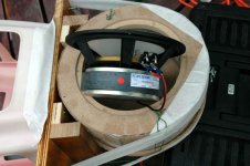
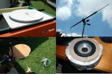
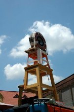
And since someone asked about the turntable, here is a better picture of it, and a medley of related equipment measurement mic, cutting test baffles, and adding extra cotton to the muffler.
I did try two things today: use a 12 in muffler (that is add extra cotton around the existing one), nd use he original 9in muffler with a short in tube in the first section closing it off for the fist 1 1/2 in on he sides sort of an ultrashort U-baffle.
After it was all done I realized I had too many reflections in ht off-axis measurements, I fired the woofer in the wrong direction. Now in the ungated data the polars are unreliable, and gated they are too clean and not comparable to the ungated graphs that I have shown here. Later I'll post at least an on axis comparison, on-axis the reflections did not do too much harm. Right upfront, both the large muffler and the short tube section did not appear to bring anything qualitatively new.
Attachments
Limited data due to limted data quality
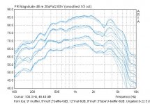
And here I present a comparison between four families of 0-7.5-15-22.5 degrees frequency responses, ungated, each progressively offset by 6 dB.
From top to bottom, always using 6.5" ScanSpeak 8543 driver on cotton-damped cylindrical mufflers:
1- 9" muffler assembly (the original muffler), no extra baffle, damping ca. 1.5" of cotton
2- same as above, but with extra frontal 12" baffle
3- 12" muffler assembly, no extra baffle, damping ca. 3" of cotton
4- 9" muffler assembly with 1.5" tube section forming a shallow "U-frame" tube around the muffler.
I am specifically comparing these 2nd, 3rd and 4th sets because they represent three different ways of achieving roughly 12"-disc-equivalent dipole separation distances, and they are compared to the first, original 9" diameter muffler.
Note: Only limited frontal polar data used because larger angle data have some issues w/o gating here.
Attachments
Re: Limited data due to limted data quality
I don't think these measurement show what you would like to think they show. Over 22 degrees the directional characteristics of the driver would be more significant that the dipole or cardioid off axis effect. At 22 degrees off axis an ideal dipole response would only be down 0.64dB. A cardioid less.
Here is a comparison of an approach similar to the annular muffler that I have used:
Form top to bottom, on axis, 45 degrees, 90 degrees, 135 degrees. Note that the gradient roll off is apparent all the way to the lowest frequency shown and that as the measurement moves to the rear the response level at low frequency decreases monotonically instead of rising again as it would for a dipole, thus indicating cardioid like behavior. I don't have a good explanation for the peak at 4.7k at 135 degrees. On axis this is a breakup mode. There may be some resonances of the back plate of the "muffler" as it is not very substantial.
MBK said:And here I present a comparison between four families of 0-7.5-15-22.5 degrees frequency responses, ungated, each progressively offset by 6 dB.
From top to bottom, always using 6.5" ScanSpeak 8543 driver on cotton-damped cylindrical mufflers:
1- 9" muffler assembly (the original muffler), no extra baffle, damping ca. 1.5" of cotton
2- same as above, but with extra frontal 12" baffle
3- 12" muffler assembly, no extra baffle, damping ca. 3" of cotton
4- 9" muffler assembly with 1.5" tube section forming a shallow "U-frame" tube around the muffler.
I am specifically comparing these 2nd, 3rd and 4th sets because they represent three different ways of achieving roughly 12"-disc-equivalent dipole separation distances, and they are compared to the first, original 9" diameter muffler.
Note: Only limited frontal polar data used because larger angle data have some issues w/o gating here.
I don't think these measurement show what you would like to think they show. Over 22 degrees the directional characteristics of the driver would be more significant that the dipole or cardioid off axis effect. At 22 degrees off axis an ideal dipole response would only be down 0.64dB. A cardioid less.
Here is a comparison of an approach similar to the annular muffler that I have used:
An externally hosted image should be here but it was not working when we last tested it.
Form top to bottom, on axis, 45 degrees, 90 degrees, 135 degrees. Note that the gradient roll off is apparent all the way to the lowest frequency shown and that as the measurement moves to the rear the response level at low frequency decreases monotonically instead of rising again as it would for a dipole, thus indicating cardioid like behavior. I don't have a good explanation for the peak at 4.7k at 135 degrees. On axis this is a breakup mode. There may be some resonances of the back plate of the "muffler" as it is not very substantial.
Some preliminary conclusions
Just to state some things while they're fresh:
- a small and circular baffle with muffler gives the cleanest off axis results. It also is the best solution w.r.t. driver separation issues. Directivity factor is around 4 dB with cardioid pattern above ca. 600 Hz and increasingly dipole like pattern below.
- but this comes at the price of an early bass rolloff, because the small muffler only acts as a low pass down to ca. 500 Hz.
- if this is acceptable then a small 9" muffler that really only consists of driver diameter plus 1.25" of cotton each side, is an easy and functional resistive box.
Attempts to prevent the early bass rolloff can be divided into two approaches:
- increasing front-rear separation distance through frontal baffle or pipe, and
- increasing damping.
Increasing separation:
- wider circular baffles provide lower midbass shelf-like extensions, with 2 drawbacks:
1- the rolloff is rapid after passing the shelf's knee, and rolloff shape is not obviously standard highpass. So EQ needs to be tricky. What is puzzling is that a larger baffle does not seem to move this shelf's corner frequency lower, all it does is to move the shelf itself higher. So it is maybe in reality a resonant peak of increasing amplitude overlaid on one and the same rolloff pattern;
2- starting at 12" baffle (2x driver diameter here) and increasingly worse the larger it is, a large frontal baffle lifts the HF in the more directional region of the driver, here >1kHz, leading to a resonant bump there plus an increasingly perverse polar pattern. The larger the baffle, the earlier the polar inversion. A standard, bookshelf speaker-dimensioned rectangular baffle gives the most irregular raw frequency and polar responses.
- tube shaped extensions work similar to circular baffle but with slightly worse polar pattern
- a driver sized small diameter tube works as well as the muffler as far as LF extension is conserned, but polar response is more uneven, lumpy, and dipole like with widening and narrowing of the pattern over the passband.
- the same tube separation extended by a damped tube extension introduces new pipe resonances and improves nothing.
Increasing damping:
- larger diameter muffler gives marginally better LF extension, but still in a shelf like fashion, not a gentle bass extension: cotton seems to works really as a resistor, and for this not too much material is necessary. HF cutoff does not change much with thickness.
- closed-off muffler only open at the back seems to be an effective LF absorber, but this destroys all benefits of the resistive box: the polar pattern becomes quasi-pistonic, but lumpier than a well designed closed box (of course one could optimize that).
___
The conclusion to me is to avoid large baffles - stay below 12" for the 6.5" driver. Additional benefit is geometric advantage re: Hi X-O driver separation. Maybe Gradient's asymmetric placement is a combination of getting small separation distance and a smeared out resonant shelf. But I don't like the idea of smearing out aberrations, it's better to avoid them or resolve them cleanly (say, by EQ). I also don't want to get into too much slanting-to-manipulate-polar-lobes business, it is tricky to optimize, tricky to measure, and I always suspect it may only work if you stay in specific listening positions.
Another conclusion is that at least for the cotton I used, the resistive part of the equation seems to work very well, and the low pass seems to have a sharp cutoff. Both resistive effect and low pass effect seem to change little with variation of cotton thickness, which is both good and bad - good: high tolerance of the building process - bad: one size fits all effect.
BTW Paul, yes felt would be interesting to try, I thought of this because that works for your large mid array, no? It's more resistive than cotton and can be layered in a reproducible way. Unfortunately all the felt I can find here is the thin stuff, sub-1mm. That's why I went with cotton first, because this I can get easily and it feels high quality and homogeneous.
It may be worth building a baffle between 9 and 12" and stuff the muffler more densely and craft the prototype really well, to see how far one can go in this direction. And then also built it as a realistic structure, with the horn on top and the bass below, to see where the effects of the adjacent objects become larger than anything in the muffler itself. So this is where I want to go next.
John, you posted while my epic was in the works...
I don't know what you mean with "what you would like to think the measurements show", I don't have definitive explanations for the reasons things look that way.
I don't see a contradiction as to the off axis responses of my previous graphs: above 800 Hz or so, driver directionality takes over, no question. Below 800 Hz, the curves from 0 to 22.5 are all bunched up very closely indeed, as you say you expect, so this does not contradict your point.
I showed these graphs mostly to show how little the different treatments really affect the bass rolloff.
MBK said:John, you posted while my epic was in the works...
I don't know what you mean with "what you would like to think the measurements show", I don't have definitive explanations for the reasons things look that way.
I don't see a contradiction as to the off axis responses of my previous graphs: above 800 Hz or so, driver directionality takes over, no question. Below 800 Hz, the curves from 0 to 22.5 are all bunched up very closely indeed, as you say you expect, so this does not contradict your point.
I showed these graphs mostly to show how little the different treatments really affect the bass rolloff.
My point was that the plots don't show anything I would not expect to see for a sealed box. I don't see anything that is indicative of an acoustic resistance loading of the back wave. There should not be ant low frequency shelf. The response should roll off smoothly with a 1st order slope off superimposed on the driver's natural response at low frequency. What I see doesn't make sense for a driver with Qts = 0.22, Fs = 30 Hz. It's like the driver is in a sealed box that yields an Fc of 400 Hz(?). Perhaps your damping is too dense. But it is not possible to draw firm conclusions w/o further off axis data. You need to look at 45 and 90 degrees, and 135 to see what is happening. If the response is cardioid like you would expect the 90 degree low frequency part of the curve to be down about 6dB (maybe a little more for a super cardioid) compared to on axis. If it's more dipole like there would be a minimum around 90 degrees and the 45 and 135 degree response would be at a higher level, though still below the on axis response by about 3dB. If the rear wave is just highly attenuated that the response at low frequency would look like a monopole.
If you look at my plot you see at all angles the response shows no sign of a baffle step "shelf", but a continued 1st order gradient roll off superimposed on the raw driver response. And you see that as the off axis angle increases the response below about 800 Hz rolls off in a similar manned but with lower amplitude, indicating constant directivity with frequency and cardioid like pattern, at least between 0 and 135 degrees off axis.
Sorry my data does not go below 300 Hz but I threw the measurements together today, inside.
John,
I don't know what to tell you because the off axis data you are talking about, that one would have to see, I already provided them 0-90 degrees forward in all but my last plot, for something like 5 or 6 different setups, and they all look different. That's a good dozen of detailed forward FR families in 7.5 degree intervals, too many to quote in links. In post 67 I explain why this last batch I can't show all off axis angles. Then, I also showed 360 degree full frequency sonograms in post 11, in post 17 and post 18. 360 degree polars? see post 13 . You asked for lower frequency full polars? I didn't replot but explained qualitatively what happes, in post 47 which also has a plot to address measured low pass effect of my muffler.
In your post 71 you also have a substantial falloff, if I extrapolate a little total falloff rom the 1000+ Hz peak down to 300 Hz, easily 10 dB, like me. No "shelf" though, and your 135 degree data look much more cardioid than mine, though your data is really very limited. As I explained in the posts cited above, mine progressively reverts to quasi dipole below 500-600 Hz and as I said in my case this may be a good thing, dipole waiting below for X-O at 300 Hz.
And to make this complete, here is a graph drawn exactly to the model of your post 71 . This is my 9" muffler, no baffle, at 0, 45, 90 and 135 degrees, tried to window it similarly to your pic, same frequency ranges and all. At lower frequencies my lines somehow get closer and the 135 line is clearly showing a come back of the rear lobe (attenuated figure eight), else though I don't see much of a difference.
Attachments
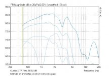
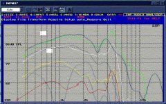
John, here I show your graph of post 71 overlaid with my own graph of the previous post, rescaled to fit. Same gating, same graph scales, pretty similar result. And I don't even know your driver, muffler, baffle, impulse type, mic, or measurement distance!
Attachments
hi,
the difference between your datas (9"muffler and johnK) could come from the materiel use for acoustic resistance (john's seems more linear with frequency,see the bump at 4.5khz,the energy stay proportional) and perpah, from the implementation of the driver (the 180°
lobe around 1500hz corresponds to some dimensions of your setup,around 9" 10",appart of that they have the same effect on polar response...
MBK,is your back wall is damped ?
MBK said:John, here I show your graph of post 71 overlaid with my own graph of the previous post, rescaled to fit. Same gating, same graph scales, pretty similar result. And I don't even know your driver, muffler, baffle, impulse type, mic, or measurement distance!
Before I can comment, in case I am missing something, your plots from Post 69:
http://www.diyaudio.com/forums/attachment.php?s=&postid=1811054&stamp=1240589645
all show a knee at between 350 and 400 Hz with some kind of plateau between 400 and 600 Hz in the on axis response. (forget the off axis for now.) I would not expect that. Your driver has an Fs of 30 Hz and Qts = 0.22. If the "muffler" were acting as an acoustic resistance I would expect to see the response (below about 1k Hz) look more like this (which is what I see in my case):
An externally hosted image should be here but it was not working when we last tested it.
So I would ask, where does tha shelf, knee behavior come from? Do you have some kind of high pass filter on the driver?
- Status
- This old topic is closed. If you want to reopen this topic, contact a moderator using the "Report Post" button.
- Home
- Loudspeakers
- Multi-Way
- Adventures in cardioid