Is it OK to do this?
No, but which transformer do you have, and what DC voltage do you need?
say I need 10V DC PS, have a transformer of 20VAC output, no CT.
Is the transformer primary a single winding, or a pair of windings?
How much DC output current do you need?
Unfortunately the primary is single winding, 115V only
Can't get 10VDC from this without dropping voltage in a resistor or regulator.
I'm thinking can get ~14VDC (half the AC output 10VAC) before regulator
I don't see that working, but use a secondary winding fuse if you plan on experimenting.
Is it OK to do this?
Yes, within limits, BUT....
The complete current loop flows through the two added resistors. If they are large, your output voltage will drop very badly. If they are small, drop is less, but you have added a LARGE extra load on the transformer, which must be very significantly over-sized.
It will be much better to take the double-voltage from a full-wave bridge and find some way to reduce it.
What about choke input? Regulator sees 18V.
yes it will work, but the whole idea here is to reuse a spare xfmer, the cost of input choker may exceed the cost of a new xfmer
sounds I better forget it
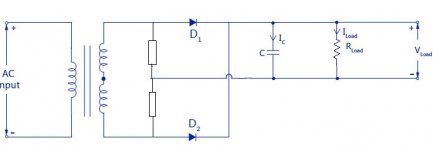
The solution is to use a current doubler; such a circuit is the dual counterpart of a voltage doubler, and in order to double the current, it also needs to halve the voltage.
Unfortunately, unlike its voltage counterpart, the current doubler cannot content itself with natural rectifiers (diodes): it also needs at least one controlled one.
This switch can be a BJT, SCR or MOSfet.
Nowadays, MOSfets are the natural solution.
Here is a first example:
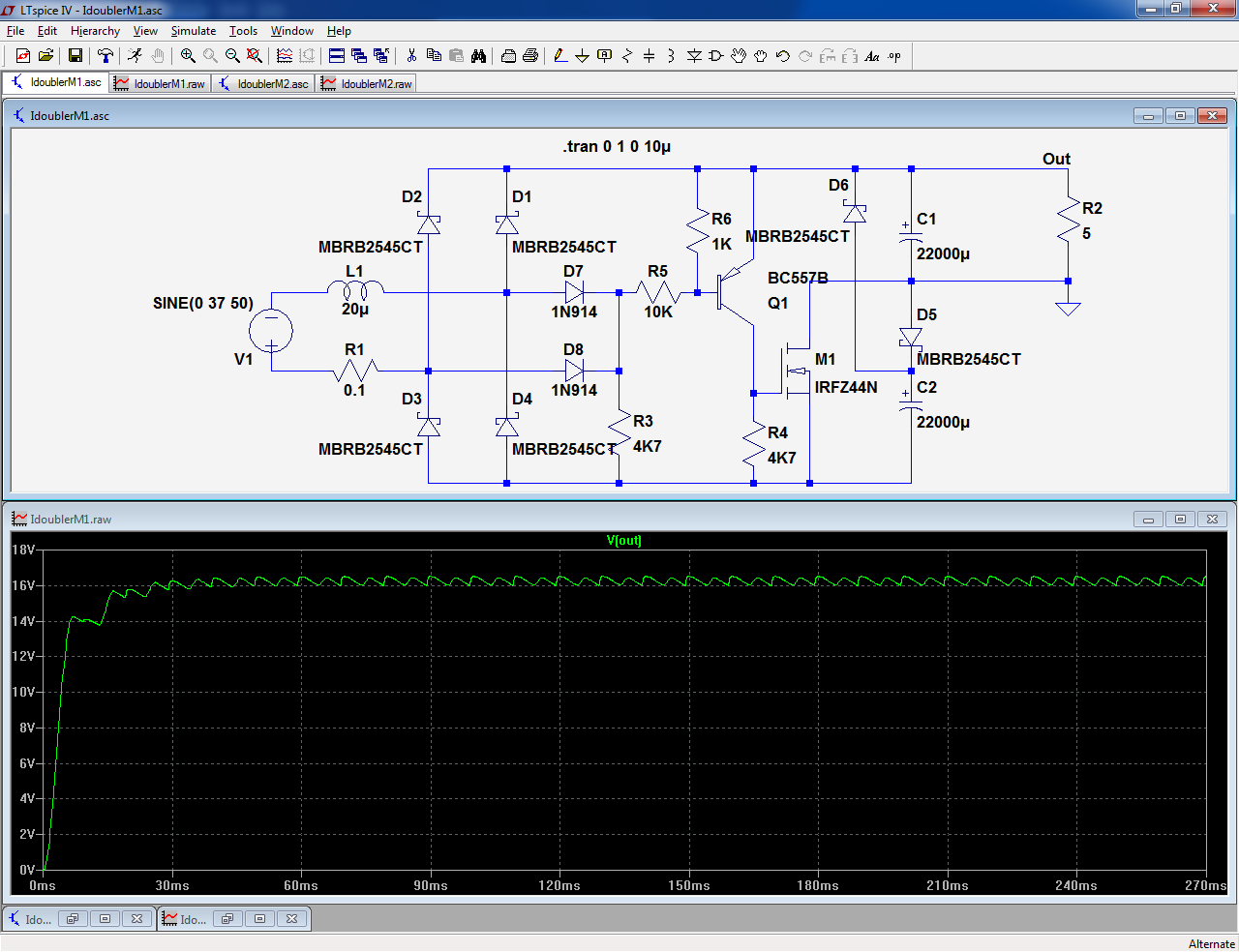
This circuit is somewhat unbalanced, because one of the capacitors plays a role in the doubler, and also as a reservoir capacitor.
If one objects to it, this can be corrected by adding a supplementary capacitor:

Note that the ripple frequency of the first example is 4*Fin
Unfortunately, unlike its voltage counterpart, the current doubler cannot content itself with natural rectifiers (diodes): it also needs at least one controlled one.
This switch can be a BJT, SCR or MOSfet.
Nowadays, MOSfets are the natural solution.
Here is a first example:
This circuit is somewhat unbalanced, because one of the capacitors plays a role in the doubler, and also as a reservoir capacitor.
If one objects to it, this can be corrected by adding a supplementary capacitor:
Note that the ripple frequency of the first example is 4*Fin
Attachments
- Status
- This old topic is closed. If you want to reopen this topic, contact a moderator using the "Report Post" button.
- Home
- Amplifiers
- Power Supplies
- Add virtual center tap to transformer