Re: Opamp out of service
Konnichiwa,
VERY EASY. Link Vout to SJ and leave Rf unconnected. Now Iout is your normal current out.
The Op-Amp now becomes a simple follower with it's input linked to ground....
Sayonara
Konnichiwa,
Elso Kwak said:Hi Phippe, Put the opamp on the AD1865 chip out of service.
VERY EASY. Link Vout to SJ and leave Rf unconnected. Now Iout is your normal current out.
The Op-Amp now becomes a simple follower with it's input linked to ground....
Sayonara
Hi Kuei Yang Wang,
So simple that we didn't saw it!!!
Thank you.
Philippe
VERY EASY. Link Vout to SJ and leave Rf unconnected. Now Iout is your normal current out.
The Op-Amp now becomes a simple follower with it's input linked to ground....
So simple that we didn't saw it!!!
Thank you.
Philippe
Hi
I have started my new dac yesterday in the evening, and it works!!!!
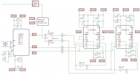
The DAc is composed of :
PSU : +5 digital, +/-5 analog, +5 clock, +5 glue logic (74act74, 74act04)
A spdif transformer, made with a IBM 93 Ohms coax/110 Ohms twisted pair balun transformer.
1 cs8414 (with the filter cell = 3.3nf // with 470ohms-220nf).
A reclock stage : it reclocks the latch signal for the ad1865 with a guido tent low jitter oscillator.
2 ad8565 : it means 2 dacs/chanel : one for data, one for data inverted. Then balanced output for each chanel.
It works as I said at the beginning since yesterday.(just on resistors at the I output of the dacs).
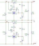
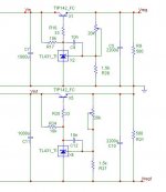
I have to build the balanced U/I. I plan to build the Nelson DI U/I stage.
The drive is a ASUS CD-S520 (ASUS 52X CD-ROM). I take the Spdif signal, and I send the 33.8 MHz clock from the dac to the drive (from which I have extracted the poor ceramic oscillator).
Then all the components are synchronous and the spdif and drive jitter doesn't matter.
The fsync signal from the 8414 can shift + or - 7 ns, the reclocked Latch signal will allways be at time.
I'll prepare shematics for all of you")
(I am waiting for your comments an critics)
Philippe
I have started my new dac yesterday in the evening, and it works!!!!
The DAc is composed of :
PSU : +5 digital, +/-5 analog, +5 clock, +5 glue logic (74act74, 74act04)
A spdif transformer, made with a IBM 93 Ohms coax/110 Ohms twisted pair balun transformer.
1 cs8414 (with the filter cell = 3.3nf // with 470ohms-220nf).
A reclock stage : it reclocks the latch signal for the ad1865 with a guido tent low jitter oscillator.
2 ad8565 : it means 2 dacs/chanel : one for data, one for data inverted. Then balanced output for each chanel.
It works as I said at the beginning since yesterday.(just on resistors at the I output of the dacs).
I have to build the balanced U/I. I plan to build the Nelson DI U/I stage.
The drive is a ASUS CD-S520 (ASUS 52X CD-ROM). I take the Spdif signal, and I send the 33.8 MHz clock from the dac to the drive (from which I have extracted the poor ceramic oscillator).
Then all the components are synchronous and the spdif and drive jitter doesn't matter.
The fsync signal from the 8414 can shift + or - 7 ns, the reclocked Latch signal will allways be at time.
I'll prepare shematics for all of you
(I am waiting for your comments an critics)
Philippe
hey Philippe,
Great work!!! Can you please post your dac schematic?? I'm quite interrested, hehe.
I got some AD1868, don't know if i can substituite with AD1865 or not. From the data sheet, they seem quite similar, and the signal input are same (LL, DL, CLK, LR, DR). I know it doesn't worth passing from AD1865 to AD1868. but it's just a test...
By the way, the problem occured on my dac, i found it and i think i'll have it fixed in these days, it was a defect of power supply!!!
Cheers
Mincy
Some photos :
Psu :
Guido clock, glue logic and old CD "oscillator"
The CD mod (see the coax from the clock):
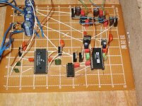
The Dac "mother board":
from left to right :
transformer, cs8414, clock card, 2x ad1865
The box (thanks to 3com )
From the top (without the cd drive)
The D1 U/I converter (one chanel)
To be continued...
Philippe
Psu :
An externally hosted image should be here but it was not working when we last tested it.
Guido clock, glue logic and old CD "oscillator"
An externally hosted image should be here but it was not working when we last tested it.
The CD mod (see the coax from the clock):
An externally hosted image should be here but it was not working when we last tested it.
The Dac "mother board":
from left to right :
transformer, cs8414, clock card, 2x ad1865
An externally hosted image should be here but it was not working when we last tested it.
The box (thanks to 3com
)An externally hosted image should be here but it was not working when we last tested it.
From the top (without the cd drive)
An externally hosted image should be here but it was not working when we last tested it.
The D1 U/I converter (one chanel)
An externally hosted image should be here but it was not working when we last tested it.
To be continued...
Philippe
My DIY AD1865 DAC
AD1865 NOS DAC completed
Hi all
I have completed an AD1865 NOS DAC. Picture below. This looks ugly compared to the DAC done by Xiaolong, for sure due to point to point wiring.
Brief on the design:
Generally based on the schematic on ptsoundlab
Separate power supplies for digital and analog sections. Power transformers are also separate. Regulators are 78xx and 79xx, one for each power pin.
I/V stage: one opa627 on each channel using the AD1865 built-in feedback resistors (not the built-in opamp). No filtering at all.
Bypass caps: WIMA MKS 0.1uF for AD1865. WIMA MKS 1uF for opa627. One more 0.33uF orange drop cap on top of opa627 (add in later, not in the picture).
Output coupling cap: 3x0.47uF Philips MKP X2 (add in later, not in the picture). These are not very good, I suspect. I have also tried Solen, Sprague PIO and dit not like the sound.
The DAC sounds very detail but not as musical as I expected.
I have also tried to parallel the bypass caps with 4.7uF ELNA Duorex II cap. This made the bass very heavy and slow down so I removed them.
Anyone have recommendation to improve it? Thanks in advance.
Attachments
MY PCB
MY PCB
An externally hosted image should be here but it was not working when we last tested it.
An externally hosted image should be here but it was not working when we last tested it.
MY PCB
The PCB work welled yesterday of.
Pack the etc. it
Experimenting the examination it is good the hereafter just sell it.
Can go to my website to go to and see:http://www.audio-sz.com
My English is very stupid.
Pack the etc. it
Experimenting the examination it is good the hereafter just sell it.
Can go to my website to go to and see:http://www.audio-sz.com
My English is very stupid.
You can use the WayBack Machine at archive.org to find things like this

link: http://web.archive.org/web/20041109...d/philips723/tubeout/ivconvertecc881canal.jpg
link: http://web.archive.org/web/20041109...d/philips723/tubeout/ivconvertecc881canal.jpg
- Status
- This old topic is closed. If you want to reopen this topic, contact a moderator using the "Report Post" button.
- Home
- Source & Line
- Digital Source
- AD1865N-K nos DIY