I received the remote volume control from altronics in Australia yesterday evening and have put it together.
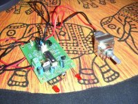
Amusingly this PCB is probably the most complicated one I have to build for the whole project! Anyway, it's a good kit and I can definitely recommend it. It was £28 delivered to my door (very quickly) and works fantastically well. I soldered it, programmed my harmony for a philips TV, connected up a 9V battery to test - it worked first try and does exactly what it says on the tin.
Pic attached.
I now have the transformers/heatsinks and the components for Nuuk's discrete buffer and PSU will be here tomorrow. The amps should also be here within the next couple of days and the drivers/xo are sitting waiting under my bed.
Will post progress details as I do them
Attachments
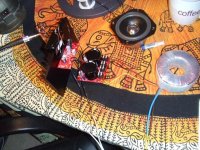
The LM3886 amps and PSUs are built and working fine. Here is a pic of one being tested playing a few things through my MA GR10s. Sounds fantastic though sounstage is severely hindered by mono operation 
The heatsinks have turned out to be overkill and barely get warm, but I suppose that's no bad thing. They were only a few pounds each anyway
The heatsinks have turned out to be overkill and barely get warm, but I suppose that's no bad thing. They were only a few pounds each anyway
Attachments
With a little help I have now completed the buffer which means that apart from the crossover the elecs of the project are finished. I'm still not completely satisfied with the grounding as the amp is not as quiet as I would like, but it is now at least acceptable.
I have posted a pic of the buffer aswell as of a test setup.
For the buffer I decided to dispense with many of the filter caps Nuuk recommends partially for space reasons but also for fear of potential oscillations that might cause problems. I did however go for the dual regulators. I have tried a couple of different transistors and preliminarily I like the ZTX1053a very much. I don't want to get into subjective sound babble, but I am now convinced that different transistors definitely do make a difference but I suppose really I would have been surprised if they didn't.
I've learned a lot in the last few days and thought I'd share a few things probably only useful to beginners but who knows.
When the soldering's done, it's useful to check the layout on both sides of the board. For some reason mistakes I missed from one side were much more obvious from the other. I know they're the same really but this did save me from plugging in a faulty circuit.
Veroboard is terrible to work on
Triple check polarity sensitive componants are in the right way
Bull clips are a great way of temporarily holding chips onto heatsinks
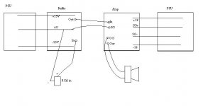
Finally, can anyone offer me advice on a better grounding... I have included a pic below of how I have things wired up at the moment which works, but as I said I definitely want to quieten it down a bit. Is it likely that the noise will be reduced when I solder things together, at the moment many of the connections are simply twisted wires helt by croc clips.
Many thanks in advance for any help offered
I have posted a pic of the buffer aswell as of a test setup.
For the buffer I decided to dispense with many of the filter caps Nuuk recommends partially for space reasons but also for fear of potential oscillations that might cause problems. I did however go for the dual regulators. I have tried a couple of different transistors and preliminarily I like the ZTX1053a very much. I don't want to get into subjective sound babble, but I am now convinced that different transistors definitely do make a difference but I suppose really I would have been surprised if they didn't.
I've learned a lot in the last few days and thought I'd share a few things probably only useful to beginners but who knows.
When the soldering's done, it's useful to check the layout on both sides of the board. For some reason mistakes I missed from one side were much more obvious from the other. I know they're the same really but this did save me from plugging in a faulty circuit.
Veroboard is terrible to work on
Triple check polarity sensitive componants are in the right way
Bull clips are a great way of temporarily holding chips onto heatsinks
Finally, can anyone offer me advice on a better grounding... I have included a pic below of how I have things wired up at the moment which works, but as I said I definitely want to quieten it down a bit. Is it likely that the noise will be reduced when I solder things together, at the moment many of the connections are simply twisted wires helt by croc clips.
Many thanks in advance for any help offered
An externally hosted image should be here but it was not working when we last tested it.
An externally hosted image should be here but it was not working when we last tested it.
Attachments
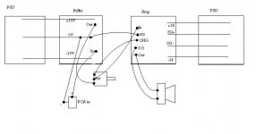
Well, after battling what I thought was noise caused by a grounding issue, it turned out to be caused by my soldering iron which was switched on on my desk. That noise is now gone (I switched it off) and I attach below for the interest of anyone else the grounding scheme I have settled on which seems to work well and the amps are now very quiet with barely any noise audible.
Also just another thanks to those who posted trying to help with that issue!
Edit: It's probably worth pointing out that in the diagram the point marked "CHG" isnt really a chasis ground since my chassis is wood, I just used the "CHG" hole on BrianGTs PCB as point of connection to the amps ground plane (which in this Dual mono setup I am effectively using as the main star ground).
Attachments
Hi all.
I had a slight change of heart this afternoon and decided to put the pot and buffer in a little black plastic box as a standalone pre.
I'm still leaving the amps in the speakers, but this way I have more flexibility and no matter which amp/speakers I choose to use I can always drop this pre in before for a buffer and remote volume control.
So here comes a couple of photos of my little preamp. The grounding scheme is... odd, but doesn't seem to cause too much trouble. It's definitely not quiet, but the noise is only audible from around 15cm from the tweeters. I'm aware many would think that unacceptable but I'm not willing to spend ages fixing it and the noise doesn't bother me as I am rarely less than 15cm from my speakers.
The box came from maplin for the very reasonable price of £7.50 and measures 22x15x7cm so nice and small.
Pics:
An externally hosted image should be here but it was not working when we last tested it.
An externally hosted image should be here but it was not working when we last tested it.
An externally hosted image should be here but it was not working when we last tested it.
- Status
- This old topic is closed. If you want to reopen this topic, contact a moderator using the "Report Post" button.