AndrewT said:Hi,
is it the minimum gain requirement of the chipamp that is the cause of the oscillation?
What about adding a unity gain stable opamp inside it's own filter loop and keep the chipamp response normal/ flat?
Hi,
I did it that way - leave the chip amp to amplify only, using a separate unity gain filter. Xplod simplified things by wrapping the filter around the chip amp. The problem is, when it's not connected to a source, it becomes an oscillator (due to positive feedback I think).
AndrewT, this design is a power amp with a limited frequency response. Hence the high gain.
Goote, you're absolutely right about the amps oscillating from rail to rail. No grounds get disconnected when the signal cable is unplugged, but the input is left floating. The oscillation never bothered me enough to simulate it (I just remembered to not turn the amp on with the cable unplugged). As I mentioned earlier, I will be using a PGA2310 for a volume control, so that should keep the input of the amps from floating. If that doesn't stop the oscillations, then I will do what you suggested, and install the resistor//capacitor.
Goote, you're absolutely right about the amps oscillating from rail to rail. No grounds get disconnected when the signal cable is unplugged, but the input is left floating. The oscillation never bothered me enough to simulate it (I just remembered to not turn the amp on with the cable unplugged). As I mentioned earlier, I will be using a PGA2310 for a volume control, so that should keep the input of the amps from floating. If that doesn't stop the oscillations, then I will do what you suggested, and install the resistor//capacitor.
similar project
Hi there - I'm doing a similar project and thought I may get some useful advice.
I've built a 3 way speaker box and am housing the amplifiers in a slot below. I've used a Rod Elliott crossover and am using 3 x LM3886 (PA150 from Alex) for the bass driver and a single LM3886 for both the mid and tweeter. The power supply and amp boards are chipamp.com. I have it up and running - problem is I can't get much gain before it starts going square wave crazy. As this is a kind of prototype, I'm just using a 18-0-18 160VA transformer which is what I had on hand. I realise it is a big ask for a small transformer to run 5 amps - but could this be my problem? The signal from the crossover seems straight and true.
Thanks for any suggestions.
Re: similar project
Hi,
Does it sound ok and everything seems alright at lower volume? If it does then it's most likely the lack of power from the transformer.
The 3 chipamps for the woofer I assume they are in parallel? Is the woofer of low impedance?
To parallel these chips you need very tight tolerances on the components (especially through the feedback). I wonder is that the problem.
Tex Houston said:
...I have it up and running - problem is I can't get much gain before it starts going square wave crazy. As this is a kind of prototype, I'm just using a 18-0-18 160VA transformer which is what I had on hand. I realise it is a big ask for a small transformer to run 5 amps - but could this be my problem? The signal from the crossover seems straight and true.
Thanks for any suggestions.
Hi,
Does it sound ok and everything seems alright at lower volume? If it does then it's most likely the lack of power from the transformer.
The 3 chipamps for the woofer I assume they are in parallel? Is the woofer of low impedance?
To parallel these chips you need very tight tolerances on the components (especially through the feedback). I wonder is that the problem.
Thanks for the reply - actually I think there must be another issue. The 3 LM3886's are paralleled yes ( http://www.diyaudio.com/forums/showthread.php?s=&threadid=65131&highlight=bpa300) and I'm driving 8 Ohm loads. I have connected my preamp directly to the PA150 board and there is no problem - only seems an issue when I use the crossover. I get the same result if I use one of the single LM3886. Unfortunately when I check the output of the crossover with the scope the signal seems fine - this makes it slightly confusing! Any more Ideas?
Re: similar project
Did you use Rod's PC board? Do you have a DC blocking cap between the filter and the amp? Earlier in this project, I thought I could get away without using the DC blocking cap, but that wasn't the case.
Tex Houston said:
I've used a Rod Elliott crossover
Did you use Rod's PC board? Do you have a DC blocking cap between the filter and the amp? Earlier in this project, I thought I could get away without using the DC blocking cap, but that wasn't the case.
Hi again - yes I'm using his board (earlier version) and power supply(PO5). I haven't used DC blocking caps - but there are 10uF caps after each output buffer. The PO5 supply is getting DC from the chipamp supply also.
As the PO5 and the PA150 board both have a single ground I have just bridged the grounds at the chipamp supply - therefore not supplying separate - and + grounds to the chipamp boards. I figured they're linked at the amp end anyway - but maybe this is a mistake.
As the PO5 and the PA150 board both have a single ground I have just bridged the grounds at the chipamp supply - therefore not supplying separate - and + grounds to the chipamp boards. I figured they're linked at the amp end anyway - but maybe this is a mistake.
Tex Houston said:
The PO5 supply is getting DC from the chipamp supply also.
As the PO5 and the PA150 board both have a single ground I have just bridged the grounds at the chipamp supply - therefore not supplying separate - and + grounds to the chipamp boards. I figured they're linked at the amp end anyway - but maybe this is a mistake.
I don't quite understand what you're saying here. The transformer you are using is 18-0-18, that's +/-25 volts rectified. The P05 uses regulators to cut that down to +/-15 volts for the filter (that's a big drop, better to have a separate lower voltage transformer for the 15V supply).
This is where I've lost you. Do you have + and - going from the power supply to the amp board?
Re: similar project
I am not too familiar with any of those units, by the way. Where can I see a schematic of the crossover?
There are also a couple of basic things that are not clear to me, from your descriptions:
Are you actually varying the power amplifier gain(s), or did you mean that you are changing the level of the input signal, via a volume control on the preamp?
Where are you seeing the square wave that you mentioned? i.e. Is the crossover fed by the preamp, with the power amps fed by the crossover, when the problem occurs, and you see a square wave at the amp output but not at its input? If so, what is the lowest peak-to-peak signal level that is being fed to the amp by the crossover, that will cause the problem to start? And what is the amp gain? (And are you sure that the crossover's output looks reasonable, compared to its input, when the problem happens? And are you connecting your scope probe ground always to the local signal ground, rather than back at the power supply, or some other central ground?)
Also, what sort of test signal are you using? If you are seeing square waves at the output, does that mean that you are using a sine wave input? If so, is the amp's output square wave frequency the same as the frequency of the sine wave input? And is the amp output square wave's amplitude basically rail-to-rail? And before the problem starts, i.e. at a lower amp input level, what are the levels of the amp input and output signals, on your scope?
Also (in case the small-ish transformer is part of the problem) can you get to a higher amp-input signal level before the problem starts when you use only one amplifier board than you can when you use all five amps at the same time? And what are the voltages between each of the amp power supply pins and an amp ground pin looking like, on your scope, when the problem is occurring?
Sorry for all of the questions. Since the problem does not occur when the crossover is not in the system, and you say that the crossover's output looks fine, even when it is in the system and the problem is occurring, maybe you should try putting something between the crossover and the amp, like a buffer, in case the amp doesn't like the filter's output impedance. For testing that, you could just use almost any cheap opamp and make a simple unity-gain non-inverting amplifier, with almost no other components. You would just wire the opamp's output pin directly to its negative input pin, and connect your filter output to the + input pin and your amp input to the opamp output pin, and apply + and - 15v to the + and - power pins. However, you should also connect at least a 0.1uF capacitor directly from each opamp power pin to ground. Note, too, that you would want to test it without the power amp connected to it, first, to verify that its input and output signals look basically identical, on your scope.
Actually, before trying a buffer, I would probably try some more-basic sanity-check types of things. Maybe try connecting a 50k-or-so resistor to ground (try 10k, too), where the filter output and the amp input are connected together. And maybe then try putting a large-ish capacitor in series with the signal, between the filter output and that resistor to ground. You should probably also try adding some various values of resistance in series with the amp input. If the behavior changes, with any of those, it might provide a clue.
Tex Houston said:Hi there - I'm doing a similar project and thought I may get some useful advice.
I've built a 3 way speaker box and am housing the amplifiers in a slot below. I've used a Rod Elliott crossover and am using 3 x LM3886 (PA150 from Alex) for the bass driver and a single LM3886 for both the mid and tweeter. The power supply and amp boards are chipamp.com. I have it up and running - problem is I can't get much gain before it starts going square wave crazy. As this is a kind of prototype, I'm just using a 18-0-18 160VA transformer which is what I had on hand. I realise it is a big ask for a small transformer to run 5 amps - but could this be my problem? The signal from the crossover seems straight and true.
Thanks for any suggestions.
Tex Houston said:Thanks for the reply - actually I think there must be another issue. The 3 LM3886's are paralleled yes ( http://www.diyaudio.com/forums/showthread.php?s=&threadid=65131&highlight=bpa300) and I'm driving 8 Ohm loads. I have connected my preamp directly to the PA150 board and there is no problem - only seems an issue when I use the crossover. I get the same result if I use one of the single LM3886. Unfortunately when I check the output of the crossover with the scope the signal seems fine - this makes it slightly confusing! Any more Ideas?
Tex Houston said:Hi again - yes I'm using his board (earlier version) and power supply(PO5). I haven't used DC blocking caps - but there are 10uF caps after each output buffer. The PO5 supply is getting DC from the chipamp supply also.
As the PO5 and the PA150 board both have a single ground I have just bridged the grounds at the chipamp supply - therefore not supplying separate - and + grounds to the chipamp boards. I figured they're linked at the amp end anyway - but maybe this is a mistake.
I am not too familiar with any of those units, by the way. Where can I see a schematic of the crossover?
There are also a couple of basic things that are not clear to me, from your descriptions:
Are you actually varying the power amplifier gain(s), or did you mean that you are changing the level of the input signal, via a volume control on the preamp?
Where are you seeing the square wave that you mentioned? i.e. Is the crossover fed by the preamp, with the power amps fed by the crossover, when the problem occurs, and you see a square wave at the amp output but not at its input? If so, what is the lowest peak-to-peak signal level that is being fed to the amp by the crossover, that will cause the problem to start? And what is the amp gain? (And are you sure that the crossover's output looks reasonable, compared to its input, when the problem happens? And are you connecting your scope probe ground always to the local signal ground, rather than back at the power supply, or some other central ground?)
Also, what sort of test signal are you using? If you are seeing square waves at the output, does that mean that you are using a sine wave input? If so, is the amp's output square wave frequency the same as the frequency of the sine wave input? And is the amp output square wave's amplitude basically rail-to-rail? And before the problem starts, i.e. at a lower amp input level, what are the levels of the amp input and output signals, on your scope?
Also (in case the small-ish transformer is part of the problem) can you get to a higher amp-input signal level before the problem starts when you use only one amplifier board than you can when you use all five amps at the same time? And what are the voltages between each of the amp power supply pins and an amp ground pin looking like, on your scope, when the problem is occurring?
Sorry for all of the questions. Since the problem does not occur when the crossover is not in the system, and you say that the crossover's output looks fine, even when it is in the system and the problem is occurring, maybe you should try putting something between the crossover and the amp, like a buffer, in case the amp doesn't like the filter's output impedance. For testing that, you could just use almost any cheap opamp and make a simple unity-gain non-inverting amplifier, with almost no other components. You would just wire the opamp's output pin directly to its negative input pin, and connect your filter output to the + input pin and your amp input to the opamp output pin, and apply + and - 15v to the + and - power pins. However, you should also connect at least a 0.1uF capacitor directly from each opamp power pin to ground. Note, too, that you would want to test it without the power amp connected to it, first, to verify that its input and output signals look basically identical, on your scope.
Actually, before trying a buffer, I would probably try some more-basic sanity-check types of things. Maybe try connecting a 50k-or-so resistor to ground (try 10k, too), where the filter output and the amp input are connected together. And maybe then try putting a large-ish capacitor in series with the signal, between the filter output and that resistor to ground. You should probably also try adding some various values of resistance in series with the amp input. If the behavior changes, with any of those, it might provide a clue.
Thanks!
Hi and thanks for the reply. The various boards I am using are the following
http://sound.westhost.com/project09.htm (Crossover)
http://sound.westhost.com/project05a.htm (Crossover P.S)
http://www.shine7.com/audio/bpa300.htm ( 3 x LM3886 board)
http://www.chipamp.com/images/ps.gif (Chipamp power supply)
I've since disconnected the PA150 board and have run the Low end signal through one of the single amps and this works fine. I was changing level to the amps via a preamp volume control - there are no gain controls on the amps. The square wave I was seeing was just the top and bottom of the sine wave getting chopped. The signal going in to the amps was fine. It seems some of your suggestions are already implemented in the crossover - I'll start putting things back together and see when I start having issues - hopefully I'll discover where I'm going wrong. I've never soldered surface mount components before - maybe I'll look again at these on the PA150 board. I'd still like advice as to how to wire the grounds - should I bridge the grounds on the power supply?
Thanks again for your help.
There are some good threads on grounding, here, that you might want to search for. Look for "star ground".
Ideally, all grounds should be kept separate from each other, until they all meet at a single "star" ground point.
Sometimes the star ground point is then connected to the actual chassis/earth/safety ground, often with a "safety disconnect" network, which usually consists of a couple of hefty diodes in anti-parallel, with a parallel reistor or 10 Ohms or so, and a parallel capacitor or 0.1 uF or so.
Success!
Hi again and thanks for helping. It seems all my problems stemmed from bridging the earths at the power supply. When I ran seperate - and + earths to the chipamps and then earthed the single earth units to chassis ground, my problems disappeared. Sounds really really good too! Now I've just gotta spend another 50 hours or so building the other crossover/amps and speaker. Will post pics when that happens!
Thanks again.
Re: Success!
Lost again, I am.
Tex Houston said:
When I ran seperate - and + earths to the chipamps and then earthed the single earth units to chassis ground, my problems disappeared.
Lost again, I am.
clarification
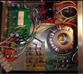
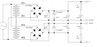
The power supply has + and - earths as in picture. The chipamp boards have connections for these and then a connection to tie back to chassis ground. The power supply for the crossover and the PA150 board only have a single earth connection. Sorry for my bad explanation.
The power supply has + and - earths as in picture. The chipamp boards have connections for these and then a connection to tie back to chassis ground. The power supply for the crossover and the PA150 board only have a single earth connection. Sorry for my bad explanation.
Attachments
Grounds, separate vs shared, star grounding, & ground bounce
I don't see why, in Tex's case, not running the separate grounds caused the massive oscillation. And right now I don't have time to analyze it thoroughly (or at all).
But, "in general", as you probably already know, having ground-return currents sharing conductors can be "a bad thing". That is one basic reason for using a "star" grounding scheme, and keeping all grounds separate.
Every conductor is just another non-ideal component. Any current in any conductor will induce a "distributed" voltage, all along that conductor, because of the conductor's parasitic resistance and inductance (and sometimes capacitance), just like when current flows through a regular component. (There are calculators and tables on the web that will give you the values of the parasitics, for specific PCB traces and wires.)
In the case of a ground-return current, we can assume that the total induced voltage appears back at the NON-ground end of the ground-return conductor. That means that the "ground" for that device or circuit will not be at zero volts (i.e. not equal to whatever the voltage is, at the "ground" end of the conductor).
And if the ground-return current is dynamic (i.e. changing), then the "ground" point from which it came will have a voltage that is changing. That is called "ground bounce".
If, for example, the ground point that is bouncing happens to be the ground reference for the input of an amplifier chip, the chip will see only that the difference between its input pin and its input ground is changing, which means that the ground-bounce voltage will, effectively, be added to the input signal. Not good.
And having a ground-return conductor SHARE the return currents from two or more different devices or circuits or sub-systems allows a ground-bounce voltage to be induced, in each place, by the ground-return currents from each of the other places. Not good.
It should be easy to see, now, that if the ground reference point for an amplifier's input stage shares a ground return with any large, dynamic ground-return current, the result could be "less than desirable", at best.
So, as an obvious example, having a chipamp's input signal's ground reference point share the ground-return conductor with the speaker's ground return, or the power supply bypass capacitors' return, would be "a bad thing".
Note, too, that while the induced voltage from a current flowing through a resistance is proportional only to the current's amplitude (Ohm's Law, V = I x R), the induced voltage from a current flowing through an inductance is proportional only to the rate-of-change of the current's amplitude (V = L * dI/dt). So, even a small current, if its amplitude changes quickly, can induce a relatively large voltage, when flowing through an inductance. The point is that dynamic return currents can make ground-bounce much worse than some people might imagine.
If you want to include these types of effects in spice simulations, I have some downloadable LTspice circuits that already have the basic setup for it, at http://www.fullnet.com/~tomg/gooteesp.htm .
Basically, I have replaced every ground symbol with an inductor and series resistance, which are tied to a star ground point. (You can right-click on each inductor, to set the series resistance, in LTspice. Or you could use a separate resistor.) I have used node labels to simplify/clarify the wiring, and so all of the ground-returns' parasitic components can be conveniently clustered together, near the star ground point, making it easy to bridge connections between different return paths (i.e. to share and un-share them), for easier experimentation.
I don't have a specific example for an amplifier circuit, on that page. Someday, I will try to come up with a simple one that shows a massive effect from a shared ground return that is cured by separating the ground-return paths, and post it there. But it would be relatively easy to copy and paste or otherwise reproduce the star ground section on your own schematics, and then add node labels for each of your ground points, replacing your ground symbols.
Sorry to have blathered-on, for so long, about that. Tex's oscillation problem may not even be related to shared ground-return currents. But it's good stuff for people to be aware of, in any case.
- Tom Gootee
http://www.fullnet.com/~tomg/index.html
MJL21193 said:Ok, now I kind of understand. I just don't see the value in seperating the ground like that.
Oh well, just a new stick for the dog to fetch.
I don't see why, in Tex's case, not running the separate grounds caused the massive oscillation. And right now I don't have time to analyze it thoroughly (or at all).
But, "in general", as you probably already know, having ground-return currents sharing conductors can be "a bad thing". That is one basic reason for using a "star" grounding scheme, and keeping all grounds separate.
Every conductor is just another non-ideal component. Any current in any conductor will induce a "distributed" voltage, all along that conductor, because of the conductor's parasitic resistance and inductance (and sometimes capacitance), just like when current flows through a regular component. (There are calculators and tables on the web that will give you the values of the parasitics, for specific PCB traces and wires.)
In the case of a ground-return current, we can assume that the total induced voltage appears back at the NON-ground end of the ground-return conductor. That means that the "ground" for that device or circuit will not be at zero volts (i.e. not equal to whatever the voltage is, at the "ground" end of the conductor).
And if the ground-return current is dynamic (i.e. changing), then the "ground" point from which it came will have a voltage that is changing. That is called "ground bounce".
If, for example, the ground point that is bouncing happens to be the ground reference for the input of an amplifier chip, the chip will see only that the difference between its input pin and its input ground is changing, which means that the ground-bounce voltage will, effectively, be added to the input signal. Not good.
And having a ground-return conductor SHARE the return currents from two or more different devices or circuits or sub-systems allows a ground-bounce voltage to be induced, in each place, by the ground-return currents from each of the other places. Not good.
It should be easy to see, now, that if the ground reference point for an amplifier's input stage shares a ground return with any large, dynamic ground-return current, the result could be "less than desirable", at best.
So, as an obvious example, having a chipamp's input signal's ground reference point share the ground-return conductor with the speaker's ground return, or the power supply bypass capacitors' return, would be "a bad thing".
Note, too, that while the induced voltage from a current flowing through a resistance is proportional only to the current's amplitude (Ohm's Law, V = I x R), the induced voltage from a current flowing through an inductance is proportional only to the rate-of-change of the current's amplitude (V = L * dI/dt). So, even a small current, if its amplitude changes quickly, can induce a relatively large voltage, when flowing through an inductance. The point is that dynamic return currents can make ground-bounce much worse than some people might imagine.
If you want to include these types of effects in spice simulations, I have some downloadable LTspice circuits that already have the basic setup for it, at http://www.fullnet.com/~tomg/gooteesp.htm .
Basically, I have replaced every ground symbol with an inductor and series resistance, which are tied to a star ground point. (You can right-click on each inductor, to set the series resistance, in LTspice. Or you could use a separate resistor.) I have used node labels to simplify/clarify the wiring, and so all of the ground-returns' parasitic components can be conveniently clustered together, near the star ground point, making it easy to bridge connections between different return paths (i.e. to share and un-share them), for easier experimentation.
I don't have a specific example for an amplifier circuit, on that page. Someday, I will try to come up with a simple one that shows a massive effect from a shared ground return that is cured by separating the ground-return paths, and post it there. But it would be relatively easy to copy and paste or otherwise reproduce the star ground section on your own schematics, and then add node labels for each of your ground points, replacing your ground symbols.
Sorry to have blathered-on, for so long, about that. Tex's oscillation problem may not even be related to shared ground-return currents. But it's good stuff for people to be aware of, in any case.
- Tom Gootee
http://www.fullnet.com/~tomg/index.html
I got back to working on this project today with the intention to finish it - come hell or high water.
I am happy to report that I have conclusively found the cause of the "crackling" sound that's been ruining my enthusiasm for this project:
MY own STUPIDITY! I was using a plumbing paste flux to make the solder flow better in places. This really works great, but there is a conductive ingredient (zinc) that was causing the problem.
Boy, do I feel dumb. Live and learn, right?
As I write this, the midrange amp is playing. I had condemned this one as completely unusable. Cleaned it up with lacquer thinner and it works like a charm.
I will pull out the others and clean them up too.
- Status
- This old topic is closed. If you want to reopen this topic, contact a moderator using the "Report Post" button.
- Home
- Amplifiers
- Chip Amps
- Active filter plus LM3886 - one board