Whoops...forgot to comment on this in the previous post.MJL21193 said:
R24 has an inductor wrapped around it and it's supposed to eliminate HF oscillation. It's actual resistance is not 10 ohms but closer to 0 ohms. It's there to keep the purists happy.
R24 (and the wire wrapped around) it is needed if you have long cable runs that have lots of capacitance. If this amp is used for active speakers, the cable runs will usually be short so you don't need it. It doesn't hurt, but in your application it doesn't provide any utility.
Neil Davis said:
Thanks for understanding that I'm not trying to find fault--just helping you get avoid some of the painful learning experiences that slowed me down in the past.
Hi Neil,
I need input, there's no pride involved. I'm the first to say I'm no expert on this. Any contribution is welcome, not just for my sake, but for anyone else reading this.
Yes, in retrospect, the ground pin on the LM3886 should have gone to signal ground. AndrewT mentioned this, and I tried it on the latest board (the really troublesome one that has since been stripped). It didn't make a difference. However, any future circuits with this chip will separate this ground.
Anyhow, the boards are bought and paid for and like I said, 4 of them are working great, so I need to get 2 more done to complete the amp.
Regarding R24: my cable run will be close to 25 feet as these amps reside together in a chassis apart from the speakers.
50r is a bit high, 4r7 to 10r is much more common. But this is not your crackling problem.Originally posted by MJL21193 The signal supply ground is isolated from the power ground on the board. I changed this back in post# 54. These grounds are separated by a low value resistor (50 ohms).
It's not there to eliminate oscillation.Originally posted by MJL21193 R24 has an inductor wrapped around it and it's supposed to eliminate HF oscillation. It's actual resistance is not 10 ohms but closer to 0 ohms. It's there to keep the purists happy.")
It's there to help eliminate the possibility of an unknown reactive load causing the amplifier stability margin to change for the worse. It does this by helping to isolate the reactive load from the Negative FeedBack input node.
It is 10r//L (inductance). If you measure this at low frequency or at DC you effectively measure the resistance of the inductor, (about 10mohm). If you measure at high frequency, the impedance of the inductor will be similar to or higher than the 10r resistor and this time you result will be <=10r.
Hi,
could it be faulty components that are not soldering well?
If the plating on the component legs is not chemically bonded to the underlying leadout material then during bending/heating the interface could break, leaving intermittant contact.
Steel wire leads would be especially bad for this problem if they have been improperly treated in the factory. Specially aggresive flux is required for soldering to steel and I suspect that is not what is used in any of the electronic solders that we normally use.
If the plating has been done correctly we don't have the bebonding problem and thus normal fluxes are adequate.
Or could it be technique?
Excessively tight (small radius) bends in the wire leads could debond any plating, even on copper leadouts.
Incorrect soldering temperature?
Have you read Holco's advice on bending their resistor leadouts?
Many manufacturers advise that any bend should be a radius and that the start of the radius must be a minimum distance from the component body.
AndrewT said:
Or could it be technique?
Excessively tight (small radius) bends in the wire leads could debond any plating, even on copper leadouts.
Incorrect soldering temperature?
I do have very tight bends on all resistors. I didn't know it could be a problem. Inserting the lead in the through hole, then cutting it off close to the board. Solder goes all around the lead, through the hole to the other side and covers the clipped end of the lead.
Soldering iron is 25 watts, no temp controll.
Hi,
solder on the reverse side of the PCB not the component side.
That's why one starts with the lowest profile components first. Working up to the tallest ones, otherwise they fall out the holes.
The excessive temperature required near the component can/will damage many if you persist in soldering on the component side.
Could excessive component temperature be the problem?
MJL21193 said:
I do have very tight bends on all resistors. I didn't know it could be a problem. Inserting the lead in the through hole, then cutting it off close to the board. Solder goes all around the lead, through the hole to the other side and covers the clipped end of the lead.
I guess I worded that wrong. I don't solder from the component side.
I'm pretty good at soldering actually. The components don't see much heating from my iron. The problem I have is the extremely tight spacing of the traces and how easy it is to bridge. Next time, I'll make the layout more spacious.
I'm sitting here typing and simulating another project, when I should be building a new board. Fear has overtaken me.

Well, I start to assemble another board. This time, I start with the amp section first - get all of the components in to give it a trial run. Only the necessary parts to make the LM3886 work.
Screw it to the heatsink, run temporary wires for power and output.
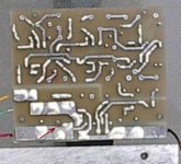
Connect the power and there's silence. Then the crackling starts, it gets worse. I look at the top and bottom of the board and I can see faint wisps of smoke coming from the bottom. I also see arcing. I cut the power and look again. There is a burn on the board between the terminal of the .1uF ceramic bypass cap.
I attempt to photograph this and what is shown below is the best I could do. The red arrow points to the area where the arcing happened. It's scorched and some of the tinning on the positive trace has been burned off.
Before I connected the power, I cleaned the bottom with a stiff bristle brush, then wiped it with a cloth. Not super-clean, but nothing on the surface.
The arcing seemed to be happening below the surface of the board. The area between is darkened.
I have since reconnected power and the arcing and the crackling has stopped.
Once again, has anyone had a similar problem? It has to be a problem with the board itself, I can see no other explanation.
Screw it to the heatsink, run temporary wires for power and output.
Connect the power and there's silence. Then the crackling starts, it gets worse. I look at the top and bottom of the board and I can see faint wisps of smoke coming from the bottom. I also see arcing. I cut the power and look again. There is a burn on the board between the terminal of the .1uF ceramic bypass cap.
I attempt to photograph this and what is shown below is the best I could do. The red arrow points to the area where the arcing happened. It's scorched and some of the tinning on the positive trace has been burned off.
Before I connected the power, I cleaned the bottom with a stiff bristle brush, then wiped it with a cloth. Not super-clean, but nothing on the surface.
The arcing seemed to be happening below the surface of the board. The area between is darkened.
I have since reconnected power and the arcing and the crackling has stopped.
Once again, has anyone had a similar problem? It has to be a problem with the board itself, I can see no other explanation.
Attachments
Hi Andrew,
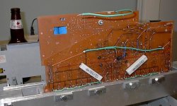
Considering all of the difficulties I've been having with these boards, I was extra careful with everything on this one. There is nothing wrong on the component side.
In the space between the solder-side pad and the positive trace, there is a burned area, it's even pitted there.
Either something is on the surface of the board that is slightly conductive, or just beneath the surface.
I have since finished this board with the remaining components and it works fine.
pinkmouse said:I'd find a new PCB supplier!
Yeah, live and learn I guess. This has been driving me mental and ruining an otherwise successful project.
This is the first time I've had boards made - everything I've done before was point to point (on a proto board or a recycled board). I've never had such problems.
Next time, I'll make my own.
Attachments
MJL21193 said:The place that I will order the boards from is:
http://www.futurlec.com/PCBService.shtml
pinkmouse said:I'd find a new PCB supplier!
You often get what you pay for in the PCB business. Futurlec isn't bad but they sure aren't the best. A little tip: increase the clearances in the layout design rules if you plan on having the boards made by a cheaper company. That decreases the chances of intermittent arcing due to manufacturing defects caused by closely spaced copper areas.
A quick fix would be to dremel out that section of the FR4 between the through hole and the copper plane. It won't be pretty but it will work.
BWRX said:
You often get what you pay for in the PCB business.
A quick fix would be to dremel out that section of the FR4 between the through hole and the copper plane. It won't be pretty but it will work.
Hi Brian,
Whatever was in there has burned itself out - I've had no problem with this board since.
I'm "once bitten, twice shy" when it comes to this kind of thing. My next board will be home-made. I'm working on a discrete design now:http://www.diyaudio.com/forums/showthread.php?s=&threadid=108860&perpage=25&pagenumber=1
I'll be making those boards myself.
Brett said:I'm glad I waited to get my boards made then, but I'm sorry for your hassles John.
Hi Brett,
It's a test of my patience, that's for sure. Luckily, the design is correct and once this crackling stops, they work beautifully.
I really couldn't handle it if there was a design flaw to boot.
As of today, I have 5 of the 6 active amps completed and operating perfectly. Just one more to build (high pass).
Building up my nerve to start it now.
The last of the drivers will arrive today or tomorrow, but the flares for the HF may be a while yet. I have some that I can subsitute short toerm, so once the month's bills are cleared, it's time to order some parts and PCBs.MJL21193 said:Hi Brett,
It's a test of my patience, that's for sure. Luckily, the design is correct and once this crackling stops, they work beautifully.
I really couldn't handle it if there was a design flaw to boot.
As of today, I have 5 of the 6 active amps completed and operating perfectly. Just one more to build (high pass).
Building up my nerve to start it now.
Going back to the crackling, my amp is doing the same. It ran for a few months with absolutely no problems, and then the crackling started. Soon after, it stopped. Fast forward another month or so (today), and I get the crackling again. MJL21193, is this how yours sounds?

That could be a a cold soldered joint or a defective device .
Re check all soldered joints and make sure that some leads are not just " covered up with solder " without actually being 'soldered'.
First step might be to blindly resolder all joints with solder. Not just reheated ! If you do this section by section , you might find the area which is causing the problem.
Edit: I just read the older posts about crackling sounds. I must be off the track .
Maybe it's a board problem.
Sorry about that.
xplod1236 said:MJL21193, is this how yours sounds?
Yes, that's EXACTLY it, and now you have confirmed my greatest fear with these - it may come back. I haven't worked on this project since my last post here, mainly because of my disappointment with this crackling problem.
Xplod1236, can you give details of your amps construction? Did you have boards made? I have been meaning to get back to this project and finish it, as the speakers are sitting here unused since I need this amp to drive them.
- Status
- This old topic is closed. If you want to reopen this topic, contact a moderator using the "Report Post" button.
- Home
- Amplifiers
- Chip Amps
- Active filter plus LM3886 - one board