Of course, I am planning to use completely separate secondaries, rated at 12VAC, 0,4A. It will be a 80VA transformer, or to keep sizes a bit down (and maybe costs a little up) I will use two separate 50VA transformers.
No earth connections, everything floating: only one at the amplifier, each pedal will be connected to it through signal cables.
I will include soft start circuit - so inrush would not be a problem. Yes, I was thinking of a 4700u - 2R2 - 4700u (2200u) filter. Maybe I will put identical caps to buy them on a scale and save some money.
I will also use the C-R-C filter to attenuate high frequency noise, not only ripple. As I have seen on some sites, the regulators are not fully capable of doing this well on their own.
And I was planning to use LM317's - I have not considered LM7809. Have you encountered any significant advantages of the LM7809 compared to LM317, which is by the way a well discussed regulator?")
The 7809 has a reduced parts count compared to the 317. Also the output voltage dos not depend on resistor tolerance. But with 1% resisters this hardly matters. It is just simpler to use and you get the same result.
Both as so low noise that they compare with battery power
One more thing, you only need about 11VDC at the input to the regulator. this means you don't need 12VAC secondaries. A 12VAC preimary limey gives about 13VDC after rectification. Maybe select the R in the CRC filter to drop the volts to about 11VDC. You really can't do this until after it is built.
I use a variac transformer to simulate best and worst case AC mains voltages and fine tune resistance values.
I'd put a 1.8k bleeder resistor across C2.
I'd also consider putting ferrite beads around the legs of R1 and, perhaps, also R2. (Here is a datasheet) and (here is a sales page) of some ferrite beads.
Me, I'd use ferrite material "73" (0 - 40 MHz). But a Really Conservative Person might use one "43" bead and one "73" bead on R1, followed by another "43" and another "73" on R2. Hey they're only 9 cents in quantity 100; it's cheap to be paranoid.
Actually I was planning to use wirewound 5W resistors to benefit from their little inductance. Or don't they have adequate inductance compared to a tiny bead?
EDIT: I am referring to Morgan Jones "Designing valve amplifiers", where he measured inductance for some wirewound resistors, ending up with values in the microhenry scale for low resistance values. Could this be adequate?
Last edited:
Some wirewounds are wound specifically to reduce inductance.
Yes, but aren't they "special"? I am intending to buy off the shelf cheap ones - anyway, I will make sure they are not exotic.
ChrisA: LM317 specs demand a Vin-Vout differential of 3V to derive most of the numbers. 11VDC would give a 2V Vin-Vout differential, since I need 9DVC output. And I think that 1 or 2 VAC extra per power supply won't be much trouble.
A 317 performs better with a higher Vdrop, that considerably exceeds the specified dropout voltage.
If you want 9Vdc and for your current the drop out is 1.9V then the MINIMUM voltage at the input MUST be >=10.9Vdc, when the mains is at lowest value and current is highest and ripple is in the trough of the waveform.
Expect that lowest useful value to be around 12Vdc for the same worst case conditions.
When mains is normal and current is normal and DC is the measured average halfway up the ripple waveform the input voltage is likely to be around 14Vdc.
A 230:10Vac 20% regulation 6VA transformer will put out a peak value of 216 / 230 * 10 * sqrt(2) * [1+20%] = 15.9Vpk when fed from lowest mains voltage. From this you need to subtract the diode drop and some sag due to non zero output current. Expect this to be around 14Vdc to 15Vdc when mains is at lowest value of 216Vac.
When mains is at highest of 254Vac, the input voltage to the reg can be as high as 254 / 230 * 10 * [1+20%] minus 500mV for diode drop ~18.2Vdc.
That is a lot of heating in the 317 using just a 10Vac transformer.
You need to do the arithmetic to determine the drop out margin and the dissipation, else you risk having a regulator that doesn't and can't do it's sole job.
YOU have to DESIGN the regulator circuit to suit YOUR DUTY !!!!!!!!
I agree [AndrewT]. Yet, the topology has to be nailed down. I've been advocating the idea double-regulation: transformer > bridge > RC lowpass > high regulator > RC > low regulator(s), one for each EFX box. They're cheap (LM317s, etc), and under single-EFX box loads, will require only the most modest heat sinks. Indeed ... mounting to the underside of a relatively thick anodized "coverplate" would provide plenty of thermal sinking. [don't forget the LM7809 regulator in the TO-3 case has case = ground, too! Nice!]
And the TO3's look so cute... like little space ships attached to the top of an anodized combo-heat-sink-and-coverplate. Tough as nails. A little straight forward point-to-point wiring inside does the trick. The LM7815 serves as the pre-regulator ... and again, it is happy to be on the same heat-sink plate. Inside this would be very clean. Run each of the outputs to its own jack (plug) and a couple feet of cord (allowing for all the usual placement/routing of the EFX boxes). It'd be slick.
Me at this point? I'd just go buy stuff - its THAT straight forward. No circuit diagram of complexity needed - other than can fit on a napkin, just to remind one's self what to hook up, step-by-step as the thing comes together.
Get a sturdy Corian or other synthetic, 3/4 cm thick baseplate;
physically place everything including the EFX boxes on it.
Square it up, measure to drill holes.
Fabricate a coverplate+heatsink.
Drill holes for regulators.
Mount all regulators.
Affix feed-through power cord (this is one of those cases where you really don't want a removable cord!).
Drill holes for fuse holder, power switch (use double-pole for safety);
Hook up transformer to line power.
SWITCH IT ON ... to make sure that nothing fissions.
Measure the A/C on the secondaries.
Wire up the bridge, initial reservoir caps, series resistors and parallel shunt (drain safety) resistor.
Measure voltages again.
Wire up all regulators on the coverplate.
Hook pre-regulator input to reservoirs.
Turn on, and again measure values on all the output pins.
Drill hole(s) for low-voltage power cords.
Route 'em.
Affix all cords & connectors.
MEASURE again that you got all the polarities right (better safe than sorry!).
Button up the project box to the baseplate.
Hook in ONE (and only one) EFX box.
Run guitar thru it, and show that it is a wonderful a power supply as envisioned.
Hook in all the rest of the EFX boxes.
Show that they all work.
Woohoo ... almost home free!
Make "corner mods" to the Corian baseplate so that the EFX boxes physically can't shift about (corner braces).
Reroute all power wires to be pretty, and wire-tie neatly.
(I like using nylon waxed wirewrap strapping here!)
Truss it all up, and get ready for gigging.
AFFIX Velcro (if desired) to undersides of each EFX and to the baseplate (for easy gigging, and so that the EFX's will "stick to the thing" semi-permanently, yet be removable. ).
It comes in rolls.
If there is difficulty having it stick to the Corian, lay down "pads" of duct tape onto the baseplate first.
Neat trick, works.
Use high quality brand that won't harden in the upcoming years.
[PS: It is a REALLY GOOD IDEA to include a couple quarter-inch jacks on the baseplate, one called "input" and another couple called "output 1" and "output 2" (or whatever). These run to short cables that allow all your EFX boxes to be pre-wired up into a "configuration". It also makes it MUCH easier to hook in the guitar and amp. Further, it helps establish a good ground, a single ground. Finally - if you're wise - you'll have put a "ground lift" switch on the device, so as to, or not to connect the 3rd power cord wire to ground. Sometimes you need a lift. Most often, you don't. ]
Now gig!
That's what I'd do. Not sit on this forum and type, type, type and type.
Wait, I just did that.
GoatGuy
Last edited:
AndrewT:
This is almost exclusively what I am doing, and Goatguy disagreed: designed the circuit for a long time thinking about literally everything.
I have calculated for my duty that a LM317 should dissipate about 2W of power during the worst case scenario. Mounting them on a 2mm or even better 3mm aluminum chassis should be enough I guess - especially since only one or two of them will dissipate that much. Let alone that I will "simulate" everything in the real world while building the project. In that manner, I have already thought about allowing the possibility of adding external heatsinks or even cooling, in case I see that anything gets warm enough during hours of test.
Frankly, I have thought everything about AC levels to ensure minimum dissipation when mains is high, and good regulation (Vin-Vout>4V always) when mains is low. I have even contacted the toroidal supplier and asked him things about regulation and his calculations.
So, for the purpose that I intend to use it, it seems to be very good planned. If you are confused about the 2W dissipation, please take into account that maximum load current is 200mA, not 0.5A as stated in the opening page. My fault, but I have stated that again.
EDIT: apart from suppresing high frequencies, the series resistors also serve for dissipating a small amount of power
Last edited:
I'm sorry, audiostrat. It is right to think it through, and to plan it carefully. Having built (literally - no exaggeration) over 250 pretty sophisticated combinations of things - power supplies, chassis, preamps, amplifiers, radio receivers and transmitters, remote-control devices and more - I guess I'm confident that what you're endeavoring to make will be a piece of cake. Just "overbuild" the platform, and the heavy-gauge aluminum "power supplies strip", so that it can serve dual-purpose as the regulator heat sink. No fans or anything else needed. No expensive transformers either!
Think about this one: F341X Triad Magnetics | Mouser
You could get both the positive and if you someday need, negative regulation out of the one transformer.
Also - you really ought to consider the "upgraded" versions of the 7809 for the fixed 9 volt regulation: they're REALLY inexpensive ($0.63/ea here in the States), and the affixing (heat-sink) tab is connected to ground. Perfect for mounting underneath (inside) the heatsink/protective circuit cover.
Again, I apologize - For little projects like this, I work out the "numbers on a napkin" (because they can be calculated in one's head!) ... then if the numbers seem realistic, I just go with it, and build one. Take a look at the sequence I listed in the posting above for how I'd go about doing the project. It really is "my general plan". Doing things in small steps, but rapidly. Breadboarding the basic idea is always a good plan, too. Got breadboard? They're cheap, good, and good for stuff like this.
GoatGuy
Actually I was planning to use wirewound 5W resistors to benefit from their little inductance. Or don't they have adequate inductance compared to a tiny bead?
EDIT: I am referring to Morgan Jones "Designing valve amplifiers", where he measured inductance for some wirewound resistors, ending up with values in the microhenry scale for low resistance values. Could this be adequate?
"adequate"? Zero might be adequate. But if you are using beads the BEST place for them is on the load end of the output power cable, as close to the effects pedal as you can. If you are building your own cables put a few turns of the wire through the bead, until you have used all the space in the central hole. Maybe 2 or 3 turns of cable.
And no, 1 uH is too tiny to do much. The reactance at 1MHz is only about 6 ohms. Not much attenuation. the typical 100 mH inductor has reactance of 600K ohms at same freq.
Power cable acts like little antenna, the bead acts as an RF choke.
I'm sorry, audiostrat. It is right to think it through, and to plan it carefully. Having built (literally - no exaggeration) over 250 pretty sophisticated combinations of things - power supplies, chassis, preamps, amplifiers, radio receivers and transmitters, remote-control devices and more - I guess I'm confident that what you're endeavoring to make will be a piece of cake. Just "overbuild" the platform, and the heavy-gauge aluminum "power supplies strip", so that it can serve dual-purpose as the regulator heat sink. No fans or anything else needed. No expensive transformers either!
Think about this one: F341X Triad Magnetics | Mouser
You could get both the positive and if you someday need, negative regulation out of the one transformer.
Also - you really ought to consider the "upgraded" versions of the 7809 for the fixed 9 volt regulation: they're REALLY inexpensive ($0.63/ea here in the States), and the affixing (heat-sink) tab is connected to ground. Perfect for mounting underneath (inside) the heatsink/protective circuit cover.
Again, I apologize - For little projects like this, I work out the "numbers on a napkin" (because they can be calculated in one's head!) ... then if the numbers seem realistic, I just go with it, and build one. Take a look at the sequence I listed in the posting above for how I'd go about doing the project. It really is "my general plan". Doing things in small steps, but rapidly. Breadboarding the basic idea is always a good plan, too. Got breadboard? They're cheap, good, and good for stuff like this.
GoatGuy
No need to apologize! Everything posted here is a valuable piece of information when viewed in the right way.
And what you say is also something that I suppose - many of you in here have implemented many considerably tough projects. It makes sense to view my little box-power one as something minor, more or less.
Right now, I don't have much room to experiment. I am quite young ang lacking equipment for the time being, so I want to spend money on something I have carefully planned in theory. And then, see whether the real implementation is within its approximations.
Of course I think no fancy heatsinking will be needed - I will experiment though, mount it on an aluminum small chassis, see whether it gets hot. Valuable observations that will save me time when planning something really crucial. Still, no time (or money
) right now for crude experimentation. But I will build one of these power supplies to test almost everything on it, and then move on to build the whole box.I love your step-by-step approach. And this is actually what I think that matters a lot: I want to go through all this making correct steps. I think everything starts at the transformer - or ideally, I think one should plan everything so that it does. Next step, go buy it - and experiment on it.
In Greece, I calculate that getting the transformer you offer will cost me about 10-15 euros less than buying a custom toroidal of 80-100VA. Many thanks for that advice though - be sure that I started from looking at what is already available, but concluded that it is really not worth it!
As for the LM317, they cost me about 0.36 euros each (from STMicroelectronics). Why bother to find anything cheaper?
"adequate"? Zero might be adequate. But if you are using beads the BEST place for them is on the load end of the output power cable, as close to the effects pedal as you can. If you are building your own cables put a few turns of the wire through the bead, until you have used all the space in the central hole. Maybe 2 or 3 turns of cable.
And no, 1 uH is too tiny to do much. The reactance at 1MHz is only about 6 ohms. Not much attenuation. the typical 100 mH inductor has reactance of 600K ohms at same freq.
Power cable acts like little antenna, the bead acts as an RF choke.
Adequate = good attenuation (this is what I meant!).
This is what I am thinking. I have two 2R2-4700uF filters in series - I think this is enough to ensure I got no actual problem with HF noise or whatever. Plot it - I think somethink like -120dB at 20kHz? I don't quite remember.
So yes, I think I could give the beads a try inside the pedals - as you say, on the load end. How about supplying each pedal with a network like: ferrite bead->10Ω->220uF. Quite typical values, and should get rid of anything that the cable picks up.
I was originally thinking of adding a mains filter with a common mode choke. Now I think it is unnecessary, given these two R-C filters.
Much better would be to use small gauge coax (stranded) cable for the power connections. The shield naturally is "ground". Works like a charm. The whole ferrite-bead thing seems like a whole lot of snake oil, when one considers the regulation and independence a 2-stage multi-regulator-output setup would deliver. But hey ... if you're going to use them, then make sure they're "transformer wound".
GoatGuy
GoatGuy
Much better would be to use small gauge coax (stranded) cable for the power connections. The shield naturally is "ground". Works like a charm. The whole ferrite-bead thing seems like a whole lot of snake oil, when one considers the regulation and independence a 2-stage multi-regulator-output setup would deliver. But hey ... if you're going to use them, then make sure they're "transformer wound".
GoatGuy
Oops! Forgot to say that! Yes, I am solely counting on coaxial cable connections.
 And small DIN connectors.
 The answer grasshopper, as to why to consider something other than the LM317 is this: because the 9V regulators are EASIER to hook up for their fixed-voltage purposing. Much easier than the LM317 for hooking to a common aluminum chassis - acting as a heat sink. All the LM7809 tabs are connected to ground, and the aluminum chassis is ground. NOT so with the 317!!! Repeat!!!
With the 317's, you'll have to provide each one of them with separate heat sinks (or notoriously finicky and fault-prone thermal insulation). Not recommended, if you can avoid it. Its fine if you have like, 1 or 2 of them (for those variable-output lines), but for your 6, 8, 10 EFX "normal" pedals, just use the straight 9 volts.
ALSO: don't forget what you're doing! You're taking cruddy power from the wall plug, which has noise from motors, computers, fluorescent lights, compact fluorescent lights, and so on; you're passing this power through a step down transformer - the higher the quality, the MORE noise it transfers to the secondary! (In otherwords, try to squash your 'custom transformer' fetish, quick!)
Now that all that noisy power is stepped down, it hits a full-wave bridge, which (noisily) switches all the oscillating power to bumpy one-polarity power. It hits a SMALLER capacitor (remember the first conversation, where this all started), to ease the switching noise; a resistor, to filter out more noise; another big capacitor - not so much as to smooth the ripple (which it does!), but also to hold a large reservoir of electrons for much higher power than average transient events by the EFX boxes. Then, (if you follow my design), you pass the power through a 15 volt linear regulator... which will heat up pretty good, but which will cut all that ripple and line noise by 80 dB or better. Then, through a couple reservoir capacitors again - merely to hold fast-response electrons! - and then to a handful of individual regulators, one for each EFX box. Remember, each of these regulators will be reducing any incoming ripple by an additional 80 dB or better. -150 dB overall!
See why there is absolutely no reason to get a more expensive torroidal transformer? It simply doesn't matter. Indeed: it makes the incoming noise actually worse, not better. So...
You say you are very young, and hint that there isn't much extra money to play around with a lot of variations. I call "bull" on that, my young friend: Every part and piece is reusable, except for the chassis you build. If you take the advice of creating a wide "pedal rack" for your guitar EFX boxes, with the power supply at one end (say), on a long, tough piece of synthetic plastic ... then you'll have a rack-of-EFX that will be easily portable (get a violin or viola bag for it!), and set-up will be a breeze.
That's why I recommend: STEP AWAY FROM THE SIMULATOR. Its time to get a bunch of stuff, and start having 10x the fun of simulation.
Now. GO get some stuff.
Pronto.
GoatGuy
I will get stuff, don't worry! As I told you, I don't like simulations better than building - believe me!
Earlier in the thread, someone posted a site talking about preregulators, saying that they don't simply add 80db+80db individually, it is a bit more complex. Still, it is true that two regulators will have better attenuation.
When I mean a custom toroidal, I refer to the windings and power! Of course and I willl not get anything that will pass serious noise. And I would like the toroidal solution for its smaller size plus the lower leakage - just don't want noise emanating close to me. These single coils pick up virtually everything. And, I would like to experiment in that manner! See whether I really don't have problems compared to an EI one.
As for noise reduction, I mentioned earlier that these two cascaded R-C filters add more than 120 db attenuation above 20kHz. Can any mains noise actually bother me then?
And I have planned a layout where the LM317's mount easily on the chassis, and I can also fix them "tightly" to it using an aluminum 1cm bar. More heatsinking than that..? As you propose, I will buy the stuff, try it, and if it does not work, change my plans! But, I think that it will work.
Earlier in the thread, someone posted a site talking about preregulators, saying that they don't simply add 80db+80db individually, it is a bit more complex. Still, it is true that two regulators will have better attenuation.
When I mean a custom toroidal, I refer to the windings and power! Of course and I willl not get anything that will pass serious noise. And I would like the toroidal solution for its smaller size plus the lower leakage - just don't want noise emanating close to me. These single coils pick up virtually everything.
And, I would like to experiment in that manner! See whether I really don't have problems compared to an EI one.As for noise reduction, I mentioned earlier that these two cascaded R-C filters add more than 120 db attenuation above 20kHz. Can any mains noise actually bother me then?
And I have planned a layout where the LM317's mount easily on the chassis, and I can also fix them "tightly" to it using an aluminum 1cm bar. More heatsinking than that..? As you propose, I will buy the stuff, try it, and if it does not work, change my plans! But, I think that it will work.
... if you're going to use them, then make sure they're "transformer wound".GoatGuy
What exactly do you mean? I thought transistormarkj proposed putting little beads around the legs of the resistors - these ones that are cylindrical with a hole, if I realised that well.
Whoops, I think you might have accidentally assumed ideal perfect resistors and ideal perfect capacitors in your simulations or hand calculations.these two cascaded R-C filters add more than 120 db attenuation above 20kHz.
Real capacitors have nonzero Equivalent Series Resistance; this parameter is often listed on the capacitor datasheet. If not, you can easily compute it from the (tan delta @ 120 Hz) number that is on the datasheet. Thanks to ESR, your RCRC filter becomes a resistive ladder network at high frequencies. The ladder's horizontal resistances are 2.2 ohms, and the vertical resistances (to ground) are the capacitors' ESR. Oops, attenuation is now quite a bit smaller.
Real capacitors also have nonzero Equivalent Series Inductance thanks to their leads and to their internal construction. Cornell Dubilier has some helpful application notes which describe how to estimate ESL. Series inductance reduces the capacitor's effectiveness at high frequencies.
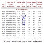
As an example, this 4700 uF capacitor from Cornell Dubilier has an ESR of 85 milliohms at 20 kHz, as shown in the datasheet image below.
One way to get greater HF attenuation, is to design the series (horizontal) legs of the RCRC filter, to have rising impedance at high frequencies. And one way to get rising impedance at higher frequencies, is to include some inductance in the series legs. You could use high-inductance resistors, or actual inductor components, or ferrite beads, or a combination of them. If you use actual inductors, make sure the resulting LC resonant circuits are overdamped (damping factor zeta > 1) to avoid oscillatory ringing; this can be accomplished by adding resistors to make the RLC circuits overdamped.
Attachments
Whoops, I think you might have accidentally assumed ideal perfect resistors and ideal perfect capacitors in your simulations or hand calculations.
Real capacitors have nonzero Equivalent Series Resistance; this parameter is often listed on the capacitor datasheet. If not, you can easily compute it from the (tan delta @ 120 Hz) number that is on the datasheet. Thanks to ESR, your RCRC filter becomes a resistive ladder network at high frequencies. The ladder's horizontal resistances are 2.2 ohms, and the vertical resistances (to ground) are the capacitors' ESR. Oops, attenuation is now quite a bit smaller.
Real capacitors also have nonzero Equivalent Series Inductance thanks to their leads and to their internal construction. Cornell Dubilier has some helpful application notes which describe how to estimate ESL. Series inductance reduces the capacitor's effectiveness at high frequencies.
As an example, this 4700 uF capacitor from Cornell Dubilier has an ESR of 85 milliohms at 20 kHz, as shown in the datasheet image below.
One way to get greater HF attenuation, is to design the series (horizontal) legs of the RCRC filter, to have rising impedance at high frequencies. And one way to get rising impedance at higher frequencies, is to include some inductance in the series legs. You could use high-inductance resistors, or actual inductor components, or ferrite beads, or a combination of them. If you use actual inductors, make sure the resulting LC resonant circuits are overdamped (damping factor zeta > 1) to avoid oscillatory ringing; this can be accomplished by adding resistors to make the RLC circuits overdamped.
My fault: I have included 100mΩ series resistance in my simulations, but forgot to say so. Still, I said 120db to give an idea of how big it is, even though it will get lower.
Yes, I think I got nice results for 50mH of series inductance - nice dumping, and even up to 100mH the peak was below 10Hz - hardly an issue. I will condsider the beads maybe. What is their equivalent behaviour? Just a series inductance?
I am planning to use some Nippon-Chemicon caps. But the following seemed weird to me:
The type I will use quotes for Ωmax=13mΩ at 100kHz (and 38mΩ at-10C, but I don't think I will get there). Still, quotes for tanδ(max)=0.22 for 20C, 120Hz. Which gives a maximum ESR of 780mΩ!
Which one should I use in my simulations? I have been able to get good attenuation with both values, but obviously there is huge difference.
And for ESL, I read somewhere about a typical value of 10nH-30nH for radial lead types. Sounds reasonable?
The type I will use quotes for Ωmax=13mΩ at 100kHz (and 38mΩ at-10C, but I don't think I will get there
). Still, quotes for tanδ(max)=0.22 for 20C, 120Hz. Which gives a maximum ESR of 780mΩ!Which one should I use in my simulations? I have been able to get good attenuation with both values, but obviously there is huge difference.
And for ESL, I read somewhere about a typical value of 10nH-30nH for radial lead types. Sounds reasonable?
- Status
- This old topic is closed. If you want to reopen this topic, contact a moderator using the "Report Post" button.
- Home
- Amplifiers
- Power Supplies
- Accurate voltage regulation