Originally Posted by AndrewT
for centre tapped transformer.
Yes !No. For this application you want all the 9V supplies to be galvanicaly isolated.,,,,,,,,,,,,,,,,,,,,,,
The question was
why are negative regulators produced?
Last edited:
A question:
Maximum DC load current that I will need is 200mA. In that manner, I apply a rule of 2x for calculating the rms current the secondary must be able to supply. Thus I would need a 12VAC, 0.4Arms secondary for supplying a 200mA DC load.
I run a simulation in spice, using a 4700u-2R2-4700u filter, for a 200mA DC regulated load. And the simulation showed a 650mArms current in the secondary! This is way off from what I had assumed to be safe.
Meaning that Pspice shows that I need a 7.8VA winding, whereas I had assumed a 4.8VA. Am I doing something wrong?
EDIT: I used the 2x rule based on reading Merlin Blencowe's "building power supplies for valve amps" - where he actually used 1.7X multiplication. I know that I use way higher capacitance, still my 2πfRLC product is within limits specified.
Last edited:
For 9V use L(M)7809 for positive polarity and L(M)7909 for negative polarity.
And preregulator for those chips are as LM317, LM337 .
.
If you read the data sheets from all of the different manufactures of the 7809 and 7909, you'll find that they have different noise specs. So, pick accordingly.
How accurate do you want the supplies ? In the OP you stated that you are building guitar effects. These, historically, are not of particularly high quality so IMHO the LM317's would be more than adequate with series pass transistors of the higher current loads.
Actually I have changed a bit my plans, in that that I will build each supply to be able to provide 200mA maximum DC load. In the first place I wanted to supply more current to use it as a generic power supply too, but I abandoned that approach. So LM317's alone will supply that current easily.
So I want accurate regulation at 9 Volts. You can say I can live with 8.8V from a crappy LM7809, but I don't think that it will cost me so much more to upgrade to LM317. They have better noise specs too.
I will post a schematic of my basic plan. As I said earlier I got some Pspice results that I did not expect, so I would be grateful if you could provide me with your opinions on the VA ratings of each supply.
")
Actually I have changed a bit my plans, in that that I will build each supply to be able to provide 200mA maximum DC load. In the first place I wanted to supply more current to use it as a generic power supply too, but I abandoned that approach. So LM317's alone will supply that current easily.
So I want accurate regulation at 9 Volts. You can say I can live with 8.8V from a crappy LM7809, but I don't think that it will cost me so much more to upgrade to LM317. They have better noise specs too.
I will post a schematic of my basic plan. As I said earlier I got some Pspice results that I did not expect, so I would be grateful if you could provide me with your opinions on the VA ratings of each supply.
It's rare that you need really accurate voltage since most opamps and good discrete circuits have fairly high PSRR. The output DC offset doesn't seem to be affected very much if the supplies are off by a volt or so. If your circuit has poor PSRR, then yeah you need highly accurate voltage regulation.
Hey - how about keeping it simple, and just solving the problem without all the worrying and consideration...
Transformer -> full wave bridge -> caps -> 20 volt (more or less) regulator at 4 amps.
Then, from there, individual LM317s for your 9 volt supplies. REMEMBER - you're talking "guitar EFX boxes" here... which are designed to take power supplies from below 7 volts to above 10 volts. (run down 9 volt batteries, or, plugged into wall-warts). This is to say, virtually every one of them will "do its thing" within that range, almost without sonic "difference". Now... in context ... how much you think the EFX box will sound different with a +/- 3% difference in input voltage? NAADAA. Not even the output levels will be affected, since most EFX boxes either have input-sensitivity, or output-"drive" knobs.
Same logic for your variable ("settable") power source. Go with your first inclination, and just leave it be.
FINALLY - puhhhhlllleeeeeeeeze put away thoughts of "more noise" / "less noise". The solution to noise has been, and will always remain the same in the world of EFX boxes. Modest (low, but not too low) series resistors and a chunky capacitor in parallel with the regulated output. Sure the output drops a few tenths of a volt ... (remember the argument above re: the importance of +/- 3%, or the lack of it) ... but if you're that concerned, the "can of electrons" approach is warranted, and a very good way to filter out HF noise - were it to be a problem at all.
The pre-regulation approach takes the wall power, which can vary from 100V to 140V (i've seen it at these extremes, here in the US), and will "tame it" to some reasonable DC overvoltage value (thru the transformer, full-wave bridge, and initial 'reservoir' caps). The regulator device(s) on that side though will need the heat-sink.
BTW - by "pre-regulating", you also get the advantage of making the pre-regulator potentially dissipate the lion's share of heat, much reducing the size-demand for the individual 9V / VariableV regulators. Two-birds-with-one-stone.
Good luck, and stop fretting. Or rather, being a guitar guy ... "Fret away", but with your nimble sausages on the fingerboard! [LOL]
GoatGuy
Last edited:
Hey - how about keeping it simple, and just solving the problem without all the worrying and consideration...
Transformer -> full wave bridge -> caps -> 20 volt (more or less) regulator at 4 amps.
Then, from there, individual LM317s for your 9 volt supplies. REMEMBER - you're talking "guitar EFX boxes" here... which are designed to take power supplies from below 7 volts to above 10 volts. (run down 9 volt batteries, or, plugged into wall-warts). This is to say, virtually every one of them will "do its thing" within that range, almost without sonic "difference". Now... in context ... how much you think the EFX box will sound different with a +/- 3% difference in input voltage? NAADAA. Not even the output levels will be affected, since most EFX boxes either have input-sensitivity, or output-"drive" knobs.
Same logic for your variable ("settable") power source. Go with your first inclination, and just leave it be.
FINALLY - puhhhhlllleeeeeeeeze put away thoughts of "more noise" / "less noise". The solution to noise has been, and will always remain the same in the world of EFX boxes. Modest (low, but not too low) series resistors and a chunky capacitor in parallel with the regulated output. Sure the output drops a few tenths of a volt ... (remember the argument above re: the importance of +/- 3%, or the lack of it) ... but if you're that concerned, the "can of electrons" approach is warranted, and a very good way to filter out HF noise - were it to be a problem at all.
The pre-regulation approach takes the wall power, which can vary from 100V to 140V (i've seen it at these extremes, here in the US), and will "tame it" to some reasonable DC overvoltage value (thru the transformer, full-wave bridge, and initial 'reservoir' caps). The regulator device(s) on that side though will need the heat-sink.
BTW - by "pre-regulating", you also get the advantage of making the pre-regulator potentially dissipate the lion's share of heat, much reducing the size-demand for the individual 9V / VariableV regulators. Two-birds-with-one-stone.
Good luck, and stop fretting. Or rather, being a guitar guy ... "Fret away", but with your nimble sausages on the fingerboard! [LOL]
GoatGuy
Well, I agree with almost everything! Of course and I don't care much about the variations in voltage. Using a good regulator is not for that reason only.
I just planned to use separate secondaries to have complete isolation. Don't you think this is better?
KatieandDad: I will use 100 ohm resistors for R1 of the regulator - so approximately 12.5 mA per regulator at idle. Combine 1 mA for a led (bright one) - 13.5 mA at idle.
I'm not sure what "I just plan to use separate secondaries - for complete isolation" is all about.
If you mean a whole bunch of secondary-windings on the power transformer(s) ... then that is ridiculous overkill. If you mean "separate LM317 for each EFX box", then that is great! Excellent isolation and freedom from cross-talk.
I also got to thinking on the commuter-bus this morning, that you'll have some EFX boxes that might want 18 volts executed as -9 : 0 : +9. Internally they might have a pair of 9 volt battery clips, but they're using the middle series connection as "zero/ground". I know of a number of much older EFX that relied on this configuration. If you do, just remember to include a bit of negative-side regulation so you can get the -9V needed, should it be required.
I'll try to draw up a circuit here at some point.
GoatGuy
I'm not sure what "I just plan to use separate secondaries - for complete isolation" is all about.
If you mean a whole bunch of secondary-windings on the power transformer(s) ... then that is ridiculous overkill. If you mean "separate LM317 for each EFX box", then that is great! Excellent isolation and freedom from cross-talk.
...
\GoatGuy
Actually, it is not overkill in this application to use separate secondaries (or separate transformers) for each EFX box. If a person uses your idea of separate regulators, the grounds are common. So you will have a common ground at the power supply, and another common ground at the amplifier via the signal leads... and then you have created ground loops and the almost inevitable hum that goes with them. Separate power supplies means only a single common ground point, the amp, so no ground loops.
I'm not sure what "I just plan to use separate secondaries - for complete isolation" is all about.
If you mean a whole bunch of secondary-windings on the power transformer(s) ... then that is ridiculous overkill. If you mean "separate LM317 for each EFX box", then that is great! Excellent isolation and freedom from cross-talk.
I also got to thinking on the commuter-bus this morning, that you'll have some EFX boxes that might want 18 volts executed as -9 : 0 : +9. Internally they might have a pair of 9 volt battery clips, but they're using the middle series connection as "zero/ground". I know of a number of much older EFX that relied on this configuration. If you do, just remember to include a bit of negative-side regulation so you can get the -9V needed, should it be required.
I'll try to draw up a circuit here at some point.
GoatGuy
Well yes, I actually mean different secondaries. You mean separate LM317's being fed from the same reservoir? I think you do because only that makes sense - if you mean separate bridges and caps, why not use multiple secondaries?
I thought that in general it is best to have complete isolation. It may not matter in effect boxes significantly, but in general doesn't it? What are its advantages?
Using separate secondaries will also allow me to use exclusively positive regulators for negative supplies (look at the previous page
), as we discussed with some members here. In case I use only one bridge and reservoir, shouldn't I use quite big a value? I was thinking about 4700u-2R2-2200u/4700u for each supply, for small (but not zero) ripple and HF filtering. In your case, isn't that cap supposed to "grow" a bit?
Actually, it is not overkill in this application to use separate secondaries (or separate transformers) for each EFX box. If a person uses your idea of separate regulators, the grounds are common. So you will have a common ground at the power supply, and another common ground at the amplifier via the signal leads... and then you have created ground loops and the almost inevitable hum that goes with them. Separate power supplies means only a single common ground point, the amp, so no ground loops.
Are you referring to loops caused via earth (by grounding this common point in the supply to earth) or something else?
EDIT: How about the rms requirements of each supply? Seems like a 80VA transformer does not suit me any nore as originally planned. Runned a simulation in PSU designer 2 using a 12Vrms transformer, 4700u-2R2-4700u filtering and 150mA DC load, and got 446mA rms supplied by the transformer. Way higher than I expected.
Last edited:
No, separate secondaries and/or separate transformers is complete overkill. Independent LM317s - one per EFX box - is the right way, the optimal way to go about solving your problem. The whole point about "common mode rejection" and "ripple rejection" has nothing - really - to do with "ripple", but the idea of large-signal A/C suppression by the regulator. Which is its job. Put a pair of them on the same supply, feeding independent loads, and not only do they suppress "ripple", but the taxing influence of each other's current draw.
Further, your approach with capacitors (4700u / 2.2R / 4700u) is OK, but puts a taxing current flow on the bridge rectifiers. Better would be 0.5R > 220 uF > 1.4R > 2200 uF > preregulator > 1 uF (spec) > 0.5R > 2200 uF > EFX regulator > 1.0 uF (spec) > 0.22R > 470 uF > EFX unit.
The initial resistor radically cuts peak current flow. The smaller initial "reservoir" cap, again being smaller, doesn't demand as much peaky current. The next R+C is your pi-section filter. Then a pre-regulator (to say "18 volts") drops things and eliminates wall-power fluctuations; removes EMI; isolates all that RFI from the bridge switching noise; delivers a relatively steady mid-voltage from where you can then add, in parallel, each of the LM317s or variable-output regulators to achieve what the EFX pedals/boxes need.
MOST of your EFX boxes will be taking "1 to 10 milliamps", because they're supposed to work off a single 9 volt battery ... for many, many hours. A single 9V battery only has like "150 ma-hours" of juice in that tiny package. So, if an average battery lasts 20 hours of practice + gig ... then 150/20 = 7.5 ma.
Further - I'd most likely use a transformer rated at 100VA (watts) overall, with a 18:0:18 (36 volt, center tapped) secondary. Using peak = 1.4xRMS, you get -25:0:+25; regulating both sides of that down to -18:0:+18 then gives a nice regulated "top-shelf" bus, from which you can then create any combination of lower voltages you need with separate regulators for the individual EFX boxes.
DON'T FORGET to put fuzes both on the input side of the transformer, but also on both the hots - the -18 and +18 hots. Protection saves many things, and you cannot believe how many perfectly reasonable little power cables leading from your regulators to the EFX boxes ... will decide spontaneously to short out internally. They're like gremlins with bad attitude.
GoatGuy
Of course the LM317 has short-circuit protection. The point though is to take the "short circuit load" - however many amps that is - off the intermediate rails, in a period of time deemed reasonable. Seconds.
Or, to just make sure the intermediate rails can indefinitely sustain the partial current caused by the short in addition to all the nominal current demands, and let 'er rip.
Either way - protection by way of fuses, or protection by inherent short-circuit-protection on the regulator, either way, it is a design point consideration.
GoatGuy
No, separate secondaries and/or separate transformers is complete overkill. Independent LM317s - one per EFX box - is the right way, the optimal way to go about solving your problem. The whole point about "common mode rejection" and "ripple rejection" has nothing - really - to do with "ripple", but the idea of large-signal A/C suppression by the regulator. Which is its job. Put a pair of them on the same supply, feeding independent loads, and not only do they suppress "ripple", but the taxing influence of each other's current draw.
Further, your approach with capacitors (4700u / 2.2R / 4700u) is OK, but puts a taxing current flow on the bridge rectifiers. Better would be 0.5R > 220 uF > 1.4R > 2200 uF > preregulator > 1 uF (spec) > 0.5R > 2200 uF > EFX regulator > 1.0 uF (spec) > 0.22R > 470 uF > EFX unit.
The initial resistor radically cuts peak current flow. The smaller initial "reservoir" cap, again being smaller, doesn't demand as much peaky current. The next R+C is your pi-section filter. Then a pre-regulator (to say "18 volts") drops things and eliminates wall-power fluctuations; removes EMI; isolates all that RFI from the bridge switching noise; delivers a relatively steady mid-voltage from where you can then add, in parallel, each of the LM317s or variable-output regulators to achieve what the EFX pedals/boxes need.
MOST of your EFX boxes will be taking "1 to 10 milliamps", because they're supposed to work off a single 9 volt battery ... for many, many hours. A single 9V battery only has like "150 ma-hours" of juice in that tiny package. So, if an average battery lasts 20 hours of practice + gig ... then 150/20 = 7.5 ma.
Further - I'd most likely use a transformer rated at 100VA (watts) overall, with a 18:0:18 (36 volt, center tapped) secondary. Using peak = 1.4xRMS, you get -25:0:+25; regulating both sides of that down to -18:0:+18 then gives a nice regulated "top-shelf" bus, from which you can then create any combination of lower voltages you need with separate regulators for the individual EFX boxes.
DON'T FORGET to put fuzes both on the input side of the transformer, but also on both the hots - the -18 and +18 hots. Protection saves many things, and you cannot believe how many perfectly reasonable little power cables leading from your regulators to the EFX boxes ... will decide spontaneously to short out internally. They're like gremlins with bad attitude.
GoatGuy
I see your points, and of course I will use separate fuses. I also know that my pedals don't draw much current - yet 2 or 3 of them actually do.
What are the real benefits of separate secondaries in general?
Thanks.
The REAL benefits of separate secondaries? Usually for a manufacturer, optimizing the windings to the real-world current load, and thus minimizing the cost of the transformer, "quantity 1,000". Say you need 1500 ma of + regulation, but only 100 ma of negative supply. Well, the usual 18:0:18 transformer has the same size wire on both legs. The "negative side" is barely used, whereas the positive side might be slightly overtaxed. Having two windings 18VAC #1 and 18VAC #2 of different ampere ratings allows less copper to be used for the negative winding. Or, it might be a 12VAC winding because there's no variable negative regulator necessary, just a -9V reg. See?
The comment from [macboy] about separate grounds and ground loops is kind of wrong: having used many an EFX box myself - simultaneously - they are arranged in chains, box A > box B > box C, and so on. The sequence of these is important if multiple EFX at the same time are desired. (In math terms, EFX boxes aren't transitive ... A > B > C is not the same as B > A > C)... Externally, the EFX rack looks like a 2 plug device: an "INPUT" jack (from guitar), and an "OUTPUT" jack or two (to amp head and stack). No ground loops present. A single secondary (as I've been talking about) on a single transformer - whether split 18:0:18 or otherwise, provides ground-loop isolation.
In short - for this application, there are no real benefits to split secondaries, or, multiple transformers.
IN FACT - I'd say at this point - don't bother with further simulations - just go buy the transformer, the parts, and gang up the -20:0:+20 clean-bus system. Use 100VA. Unless you've got a monster box that takes zillions of milliamps, it'll be enough. Get it all mounted in such a way as to have a lot of air-flow, and a good solid cage to protect against people stepping on it, dropping sh*t on top of it, etc. Tough construction is your friend, here.
Really! Transformer, bridge rectifier, caps, resistors, heat sinks, switches, fuse holders, fuses, mounting plate, cage. LEDs, regulators, connectors, more switches. This is the project, not yet another PSU "simulation".
GoatGuy
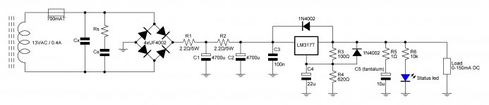
9VDC LM317 power supply schematic
As promised, I attach the schematic I have come up with so far.
Nothing very special - secondary, slow blow fuse, snubber, bridge, two R-C filters for smoothing and then the LM317 circuit. Which uses the 100n film cap at the input for transients, and an R-C combination at the output for stability. I have chosen a 10uF tantalum cap in series with an 1 ohm resistor. Plus protection diodes.
All resistors unless specified are 0.25W metal film. Maybe I will put 0.6W metal films if I can get them easily.
Any opinions are welcome!
Attachments
Last edited:
I'd put a 1.8k bleeder resistor across C2.
I'd also consider putting ferrite beads around the legs of R1 and, perhaps, also R2. (Here is a datasheet) and (here is a sales page) of some ferrite beads.
Me, I'd use ferrite material "73" (0 - 40 MHz). But a Really Conservative Person might use one "43" bead and one "73" bead on R1, followed by another "43" and another "73" on R2. Hey they're only 9 cents in quantity 100; it's cheap to be paranoid.
- Status
- This old topic is closed. If you want to reopen this topic, contact a moderator using the "Report Post" button.
- Home
- Amplifiers
- Power Supplies
- Accurate voltage regulation