[emoji23].
Another n00b question, which type of class A is ‘George’ ? Single ended or push pull? How can you tell the difference?
Dan
he's squeezing with two hands so answer must be PP

Bridge balanced monoblock configuration - I built up the 2nd amp and am listening to the pair now. (XLR input)
Wow.
Wow.
WOW!
For such a modest circuit with lots of choices and tricks to making it simple, beginner-friendly, and bulletproof, these have no right to sound this good.
Papa is a genius.
Period.
How dow it sound compared to the SE configuration?
More dynamic caused by more power?
It will probably depend a lot of the speakers used.
The distortion pattern will look a bit different?
he's squeezing with two hands so answer must be PP
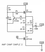
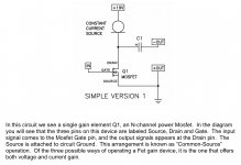
ACA is Single-Ended amp with his CCS
Attachments
..... his CCS
whose current contribution , in overall seesaw fun , is 33% minimum
are those just fancy questions , or really relevant?
you don't know how to predict THD spectra of two (dominantly) SE stages bridged , but you know to ask for group delay
I assume THD will be less in the bridged version with less 2nd harmonic....but is 2nd harmonic still the most dominant?
Based on 6L6's "wow wow wow" I was interested in knowing how the sound changed from SE to bridged mode.
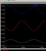
About group delay I am interested in knowing how much the output cap will "destroy" a constant group delay as an ecap in this size will typical have negative phase at low frequencies but shift to positive phase at higher frequencies. I would expect this error to be cancelled in bridged mode.
When I get the components and get the ACA assembled I will measure e.g. a 20 Hz sine and a 20 kHz sine and then compare phase difference between input and output. Will see how much it differs from 180 degree.....then I can come back and tell if the ACA if phase linear or not.......at least I will learn something......I am far from expert but learn every day......and get some feedback from real experts can give me a "jump" in the "expert direction" without spending too much time reading......
whose current contribution , in overall seesaw fun , is 33% minimum
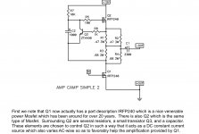
In the extract of FW ACA article I read Q1 mosfet is operated SE

Q2 help AC-wise for Q1 but do that mean ACA is a PP amp....?
Attachments
he's squeezing with two hands so answer must be PP
of course that ACA is SE , but special sort of , same familly as Aleph
What we call that sort of amp ?
SRPP = SEPP or better say ACA is operated in SE Mu Follower ?
Interesting stuff

Coolnose - Yes, please post photos!
Everybody - Please feel free to post photo in the thread! We'd love to see all of your ACAs.
Soundhappy - The ACA's CCS is most accurately called a Mu-Follower. The output node between the power resistors and the CCS on top of those resistors allows the CCS to vary into the load to help the output device drive it. (More power, more damping)
MEPER - Have you built your ACA yet? I'm curious to hear your impressions with all the fancy and expensive capacitors.
Last edited:

Bridge balanced monoblock configuration - I built up the 2nd amp and am listening to the pair now. (XLR input)
Wow.
Wow.
WOW!
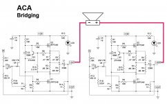
Since the positive output on the ACA is grounded, I assume that one uses the negative outputs for bridging. Is that correct?
Pic below is how I understand it. (ACA #1b schematic used)
Attachments
Coolnose - Yes, please post photos!
Everybody - Please feel free to post photo in the thread! We'd love to see all of your ACAs.
Soundhappy - The ACA's CCS is most accurately called a Mu-Follower. The sensing node between the power resistors allows the CCS to vary into the load to help the output device drive it. (More power, more damping)
MEPER - Have you built your ACA yet? I'm curious to hear your impressions with all the fancy and expensive capacitors.
I have just paid the custom fee so the packet containing the ACA components can be released. So next week I will pickup the packet. It will probalby take some weeks to finish as I also want to build 2 x 24V old fashioned PSU for it and these components are not ready yet (should be ready to pick up next week or so). I think the PSU will take the most time to build.
I have not decided yet which capacitors to use......still thinking and I have done some measurements. I will also measure the 3300 uF cap in the kit.
The 10 uF I can get one that measures close to -90 degree from 10 Hz to 20 kHz.....it is much more difficult with the 3300 uF cap. Even bypass it with "better" smaller caps does not effect the measurements much.
I have the ACA chassis which came from Italy. I have been thinking on how to mount the big caps......
....simple straps is one way to do it.The plan was to only mount one ACA in each chassis so I have space to mount the big caps and then have the ACA as SE mono blocks.
I will post some pictures when it starts to look like an amp......
I have not decided either which input impedance I should go for.....10k, 20k or maybe 47k if that is possible. There is probably a limit for the values for the feedback resistors. More noise maybe if they get too large.....or maybe unstable amp.
But that is part of the project.....to learn something. Therefor my amp may take a bit longer to finish than others.....
Yes, negative outputs.
Right is +, Left is -
Thanks for confirming, 6L6. I think a good connection between the two positive outputs is also a must, especially if insulated RCA sockets are used. Can't rely on connection to the enclosure.
you can call output nodes "Hot" and "Cold"
"cold" is on GND
then there is no confusion
of course , for bridged , you're using two hots to connect speaker
That's a 'cool' way of putting it. Thanks ZM

- Status
- This old topic is closed. If you want to reopen this topic, contact a moderator using the "Report Post" button.
- Home
- Amplifiers
- Pass Labs
- ACA V1.5 Illustrated Build Guide