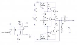
I'm looking at that R7 between the opamp output and the minus supply - it doesn't look needed to me. And the thing looks scary without the emitter resistors. They at least partly reduce the chance of thermal runaway in the output devices. Being darlingtons (two transistors in each case), both the driver's and output's Vbe's will drop as they heat up.
It is possible to leave out R7, but then the current goes into the opamp. Nothing wrong with that, as long as it is within limits. But it does look a bit strange.
You're probably right about the emitter resistors. I would recommend putting them in for anybody building such a thing. I would also add a Zobel output network and decoupling caps. Oh yes and I would replace the diodes with a Vbe multiplier.
Attachments
haha, I had downloaded LT spice before and it scare freak out of me. (too much thing to learn) And I'm now using TINA(Texas instrument's simulation) based on SPICE, but its easier to use than LT spice a bit, but still not familiar with it.
Is there any tutorial about using LTSpice for Audio usage ? (making discrete amplifier)
I could see LTSpice it widely welcomed.... I also tried P-Spice yesterday, and cracked my head to find how to import models...(NJL3281/1302,etc)
Is there any tutorial about using LTSpice for Audio usage ? (making discrete amplifier)
I could see LTSpice it widely welcomed.... I also tried P-Spice yesterday, and cracked my head to find how to import models...(NJL3281/1302,etc)
I don't think LTSpice is so hard to learn. Just start with some really simple circuits and build up. Eventually you will learn how do noise analysis and FFT's. Very useful. The User Interface is a bit off standard, that is true. Overall the learning curve is not that steep.
I don't think however the LTSpice community is all that helpful or friendly. There is no one sharing component model libraries they have built up over time to help others starting out. It is each to their own.
I don't think however the LTSpice community is all that helpful or friendly. There is no one sharing component model libraries they have built up over time to help others starting out. It is each to their own.
haha, I knew that. But is there anyway to import model in bulk ? (using TINA, I import one by one.......There is so much !) those community's problem.... I think its still good that share out. (able to obtain)
Well.... I think only 2 things I'm not sure using LTspice, first is Analysis, then second is terminal to analysis (jsut the whole chapter of analaysis would do a good job)
The problem is I can't find how to define the output, input and how to put a oscillator in that particular component in order me to see the results.
http://www.diyaudio.com/forums/solid-state/188736-spice-simulation.html#post2567721
I think this is nice for simulation learning using LTspice (currently running through it)
I think this is nice for simulation learning using LTspice (currently running through it)
I'm going to build a symmetrical amplifier with minimum component ...
go ahead,
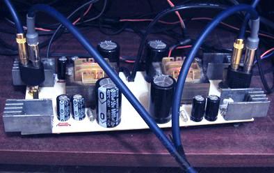
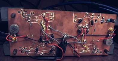
it is built (IRF540/9540 version), sound is gooood,
low out impedance preamp or buffer would be good choice at the input...
http://www.diyaudio.com/forums/solid-state/57892-tcj-evolve-simply-good-amps-idea.html
haha, I had downloaded LT spice before and it scare freak out of me. (too much thing to learn) And I'm now using TINA(Texas instrument's simulation) based on SPICE, but its easier to use than LT spice a bit, but still not familiar with it.
Is there any tutorial about using LTSpice for Audio usage ? (making discrete amplifier)
I could see LTSpice it widely welcomed.... I also tried P-Spice yesterday, and cracked my head to find how to import models...(NJL3281/1302,etc)
TINA is good, but I don't know how to add models to it. The limitations imposed by the free version of Pspice means you won't be able to run big circuits with it. LTspice is quite easy to customize.
haha, I DID know how to add model into TINA, and I manage to customized to LTspice, but currently having some problem in utilizing my time.....TINA is good, but I don't know how to add models to it. The limitations imposed by the free version of Pspice means you won't be able to run big circuits with it. LTspice is quite easy to customize.
Will continue 'absolute zero' after I properly manage my time. (sometimes I hate it why only 24 hours per days, and alot of people around me say 24 hours is wasting or too much....)
hm... just think of something. Why is it necessary to insert a input decouple capacitor (usually between 1uF and 3.3uF) ? Does it for safety purpose, like prevent DC into source component ?
What is different between using and remove that capacitor ?
why don't put one also in the input ground connection ?
What is different between using and remove that capacitor ?
why don't put one also in the input ground connection ?
Do you mean an input coupling capacitor? It isolates DC conditions between the two circuits, while passing the AC signal through. Although it has a safety function, the main idea is to allow you to design the two circuits separately and have convenient source switching. Usually no need for one in the ground connection and one there might increase hum.
ah... srry to mention decouple instead of coupling.
just think that might add a capacitor between input ground for safety purpose or something like isolation purpose. (protect against DC problem) why would it induce hum/noise ?
Usually what value is suitable ? that is enough to prevent audio frequency cutoff, and adequate DC protection.
Just extra question. Is it possible that DC bias of input transistor is then amplified to output transistor for bias current ? (mean no DC connection from supply to base)
hm.... i have studied basic topologies, but seems doesn't much understand about those input impedance thingy. It said that some arrangement offers high input impedance, is it true ?
Example of common-collector have high input impedance, while common-base have low input impedance.
Example of common-collector have high input impedance, while common-base have low input impedance.
- Status
- This old topic is closed. If you want to reopen this topic, contact a moderator using the "Report Post" button.
- Home
- Amplifiers
- Solid State
- [Absolute Zero] Design Amp with minimum component (understanding too)