
I've moved the Vellemann discussion here to Sakis' thread here,
http://www.diyaudio.com/forums/solid-state/164756-p3a-comparsion-table-long-10.html#post3487303
If you want a new thread starting for it then just say so
")
and maybe MJE340/MJE350 replacing 2SA1110/2SC2590
ZTX450/550 'replacement' might be BC546/556
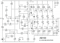
PASS AB100 - Minimalist improved schematic
Feel free folks to adopt...
Resistance values are now in more familiar coding.
The "missing ground" has been added.
Crossing lines have been 'broken-gapped' for clarity.
Zener has a Vz value.
No adjustments made to actual values.
Subtle... but a bunch easier to "stare at". And that darn input ground insertion prevents the old-timer's "where the heck is the operating point of the zener?" problem.
GoatGuy
Attachments
Feel free folks to adopt...
Resistance values are now in more familiar coding.
The "missing ground" has been added.
Crossing lines have been 'broken-gapped' for clarity.
Zener has a Vz value.
No adjustments made to actual values.
Subtle... but a bunch easier to "stare at". And that darn input ground insertion prevents the old-timer's "where the heck is the operating point of the zener?" problem.
GoatGuy
Now if you could add the values to Tinnitus's drawing it would be even easier to read!
Now if you could add the values to Tinnitus's drawing it would be even easier to read!
WHICH tinnitus drawing? He's come up with 2 or more.
Its funny - maybe 'cuz I live in The Colonies (AKA America) - but I get weird feelings when I look at resistors, drawn correctly by IEEE and EU standards, as little square boxes, instead of zigzags. Every OTHER component in electronics is a symbolic representation of its "principle of action". Capacitors are separated plates, transistors are bases with emitter and collector points touching (like Schottky's original!), diodes are symbolic "electrons stop here", coils look ... like formalized coils. Transformers are obvious, even tubes are pretty clear. Switches - bars that switch, etc.
Well, "resistors" are accurately zigzags! Originally almost all wire-wrapped, the notion is, "a bunch of crumpled up conductor, thin, that gives resistance". By comparison, the square box is ... counter to all the other symbols. According to many sources, it was adopted in the 1970s because "it is easier to draw both for draughtsmen and early memory-limited computers". It hardly seems appropriate. The zigzag IS the correct representation, and the little white box ... just "lies": many little boxes in digital electronics especially harbor marvelous and obscure functionality. Indeed, one does a disservice to a digital circuit schematic of any complexity using little square boxes for pull-up or balancing resistors.
This is why I'm also not inclined to annotate Tinnitus's drawing. Call me provincial, but I think Nelson Pass's original AD2000 drawing (with broken gap crossovers) is entirely clear. And I like zigzags for poor conductors. Gotta make those electrons run, run, run! That way they get tired.
GoatGuy
Last edited:
so that my drawing remains worthless, and not floats around the net with wrong values or text, I have intentionally stayed away from adding any kind of values, or text
but feel free to print it out and use for your own personal use
I hope thats ok, and clear enough
same goes for the resistor chart, no text added
use as you wish
but please refer to original schematic for correct values
Resistance values are now in more familiar coding.
The "missing ground" has been added.
Crossing lines have been 'broken-gapped' for clarity.
Zener has a Vz value.
Now if you could add the values to Tinnitus's drawing it would be even easier to read!
well, for that you deserve at least 'something'
I guess component numbers will be ok
btw, since bias transistor Q8 is a TO-92, Im planning a small board for it
it will be mounted with small alu plate with hole for the transistor
the hole bias curcuit can then be mounted on the main heatsink
drawing will come soon, ofcourse
Attachments
 MJE340/350 does not appear to be very popular
 but I have a few 2SC5171/2SA1930...maybe they would do ok
maybe, maybe not

getting tired
final...but still needs careful checking
Attachments
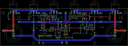
AB100 PCB
Trying make layout, Vas using BD139/140 and 3 pair output, for DiyAudio UMS .
Schematic
PCB
Didiet
NB: for some unknown reason, my pcb link to imageshack got error
Trying make layout, Vas using BD139/140 and 3 pair output, for DiyAudio UMS .
Schematic
An externally hosted image should be here but it was not working when we last tested it.
PCB
An externally hosted image should be here but it was not working when we last tested it.
Didiet
NB: for some unknown reason, my pcb link to imageshack got error
Attachments
Last edited:
Wow!!! That is a fantastic first layout!! Thank you Didiet!
What are the current PCB dimensions?
And a question for the community -- Does anybody know if Q3, Q5 Q6 need to be individually heatsinked and/or need to be on the main heatsink to track the output's temperature?
Thank you Didiet!What are the current PCB dimensions?
And a question for the community -- Does anybody know if Q3, Q5 Q6 need to be individually heatsinked and/or need to be on the main heatsink to track the output's temperature?
A few quick answers.
(deleted)
The 1n4004 (or any diode) is for current limiting - they will not get burned
out with the little current available from the front end.
The bias transistor for the output stage is best mounted where the heat is.
(deleted)
Dimension 74.14 x 251.44 mm (Like Honey Badger, more or less)
Didiet
In my repair bench stands A stasis Nakamichi PA 7 first series
Since i am an sziklai lover and very familiar with the principal of operation of the circuit i will have to say that i simply admire the circuit and i find it innovative for the time designed and farther more use of technology that was unknown at the time and excellent choice and use of semis ...
When i first looked at this thread i was expecting a stasis probably with no more power than 60 or 100 W but an advanced circuit may be 10 times better than the stasis ...
Even though Papa has given so many things to the community in the Class A it looks that his brain is absorbed by the heat and class AB lovers will have to wait for a feature spark ...
One way or another every member of the forum including me will have to pay his respects to Papa since just a couple of words from Papa equals to 10 theory books available in the market .
Thanks Papa !!
... how does it sound?
I guess we will never know
One way or another every member of the
forum including me will have to pay his respects to Papa since just a couple of
words from Papa equals to 10 theory books available in the market .
Thanks Papa !!
Thank you.
High Quality Home Theater Amp
Can this circuit be run a few watts into class A and then into AB?
I would like to make a home theater amp with 5 channels or more.
I was thinking of a Class A/AB, 75 to 100w, 2-stage, Mosfet output, 4 ohm capable circuit, but why reinvent the wheel, if this circuit can be at least be biased for Class A to a few watts.
Anyone still working on boards?
Thanks,
Vince
Last edited:
Member
Joined 2009
Paid Member
This amplifier is interesting also because it uses power Darlingtons - they are not very popular and I never heard anybody say they can be used to achieve good sound.
Can power Darlingtons be used to achieve good sound ?
I have a bunch of Sanken power Darlington devices in To3p packages (1560 & 2390) from a disassembled HT receiver, so they are not matched. But with higher source resistors that may not be an issue.
What about a BA3 style output stage, can be used with BA1/2/3/ input stage. Instead of MOSFETs we use Darlingtons and bias them at optimal AB, maybe add a pre-driver and we have a triple that's easy to driver.
One could decide that the first Watt should be all Class A, so we want at least 500mA idle current (8R load). Say we can get away with 0R47 source resistors then we need 'only' 9 or 10 output pairs. With +/- 50V rails, imagine what it could do
Hmmm, I have the HT heatsink with holes ready for the 7 output pairs already....
Just thinkin'....
Last edited:
- Home
- Amplifiers
- Pass Labs
- AB100 Class AB Power Amplifier