She's Singing Again...
PITBUL: Thanks for the clarity.
MOOLY: Thanks for this description. I will have a go and see what I find.
As an aside, we hooked-up the old girl today and sat down for a listen - the first time in a few years.
Boy! It's good to have her back in business...
With her meagre 10W + 10W Class-A output, the Z501 easily bettered our excellent CREEK CAS 4040S3 40W + 40W Integrated, which we have been enjoying so much lately.
I'm not sure what the clever LUXMAN crew did with this Avance Z501 amp, but for us - who are usually tube amp listeners (LEBEN) - the Z501 is probably the best solid state amp we have ever heard; or at least neck-and-neck with the nice FIRST WATT J2 we owned for many years.
Definitely worth seeking out - or (perhaps) worth a clone/scratch-build!
")
PITBUL: Thanks for the clarity.
MOOLY: Thanks for this description. I will have a go and see what I find.
As an aside, we hooked-up the old girl today and sat down for a listen - the first time in a few years.
Boy! It's good to have her back in business...
With her meagre 10W + 10W Class-A output, the Z501 easily bettered our excellent CREEK CAS 4040S3 40W + 40W Integrated, which we have been enjoying so much lately.
I'm not sure what the clever LUXMAN crew did with this Avance Z501 amp, but for us - who are usually tube amp listeners (LEBEN) - the Z501 is probably the best solid state amp we have ever heard; or at least neck-and-neck with the nice FIRST WATT J2 we owned for many years.
Definitely worth seeking out - or (perhaps) worth a clone/scratch-build!
That's Settled Then...
Thanks TVI.
Actually, it's strange seeing an identical amp wired slightly differently - after staring at ours for so many weeks.
Well, it's settled. 40 years is a pretty good innings and the amp still sounds magic - but these are obviously original fit capacitors and they're gonna need to go.
Seeing as I am going to be working on the Power Supply Board area to get to the caps, I will probably replace the high-value Metalised Resistors at the same time.
Another push awaits...
Last edited:
Eumig m-1000
is pretty similar too, nippon chemicon e'lytics
just found this page
Eumig M-1000 and this pic
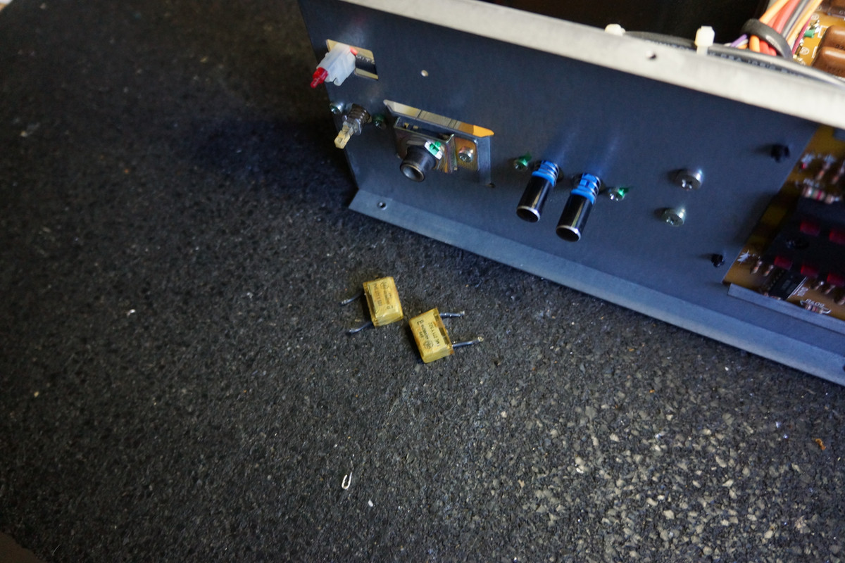
If your amp has these check to see how cracked they are, the can start smoking and oozing black burnt epoxy, don't panic just change them when you can to new x2 class polypropylene caps same value, had this happen to me a few time and the smell stays with you

regards
james
is pretty similar too, nippon chemicon e'lytics
just found this page
Eumig M-1000 and this pic
If your amp has these check to see how cracked they are, the can start smoking and oozing black burnt epoxy, don't panic just change them when you can to new x2 class polypropylene caps same value, had this happen to me a few time and the smell stays with you
regards
james
Attachments

RIFA PET Caps...
Thanks TVI.
Fortunately, I haven't spotted any of these types of caps in my gear.
Having considered all of the options and factors - particularly space on the board - I think I'm gonna stick to +105-degree Electrolytics for this project.
This also allows me to keep the Capacitor leads as short and as close together as possible, to minimise any induction factors.
The original designers obviously knew a lot more than me!
Tonight's Learnings...
Tonight, enough parts had arrived for me to swap-out the four 39K-Ohm 1W Met. Ox. Resistors in the PRE DRIVER section.
(I assume this area is responsible for Voltage Gain, but would welcome correction on this...)
Because of the massive amount of heat-impact on the circuit board surrounding these Resistors, I elected to try some Japanese ROX3S 39K-Ohm 3W Met. Ox. replacements - in the hopes that they would better handle the potential heat this machine outputs, when the Bias Idle is correctly set.
The swap-out went very well and I elected to replace the frayed braided "sleeve" on each Resistor lead with a clear PTFE sleeve. These great little sleeves - precut to size - also helped me to keep each Resistor at precisely the right height, while I soldered. In this way, I kept the new Resistors at the same height as their predecessors.
Once the swap-out was complete, I decided that it would be good to stop there and make sure that the old girl was still operational. I was also curious to see if this change impacted the sound.
Upon power-up, there were no problems at all and the amp stabilised quite quickly. Once the music was playing however, it was immediately apparent to both my wife and I that something special had been lost in the sound department. Everything was just way too smooth. The sparkle in the tops was gone. Sure, it still sounded good and the essential nature of the amp still came through, but this was definitely a backwards step.
Upon further thought, I guess I should have anticipated this outcome, as I am planning to do exactly the same thing in the POWER SUPPLY section - replacing 1W resistors with big and "lossy" 7W (Wirewound in this instance) Resistors in an effort to block "unwanted" noise. I guess the bigger Resistors in the PRE DRIVER section have achieved the same thing, at the expense of frequency extension; especially in the tops. So perhaps I have blocked "wanted" noise? LOL!
Alternatively, this could simply be a typical sonic result after changing ANY critical signal path components - and the problem will simply resolve itself as the new Resistors "burn-in". I'm not experienced enough to know the answer right now, but somehow, I don't think I can buy this theory.
What do others think?
If my suspicions are correct - and the 3W Resistors are the problem - I will probably drop back down to 1W Resistors, but with a view to mounting them higher and further away from the board, in an attempt to help with cooling.
Does this idea have merit? Or will there be other losses with longer Resistor leads?
It could be too, that perhaps there is a superior type of Resistor out there - Caddock Thick Film or something exotic - which might offer superior results compared this Met. Ox. type.
Again, what do others think?
One other incident occured tonight. I thought I was quite fortunate to find four new 3W Met. Ox. Resistors that all measured exactly 38.6K-Ohms - out of a pack of 10. So, a perfectly matched set that were near enough to 39K. Strangely - after being soldered into place, and checked again - 1 of the 4 new Resistors had dropped down to 37.8K-Ohms. The other 3 new Resistors had held their exact pre-ciruit value, once soldered into the circuit. Weird.
Can anyone shed some light on what might have happened here? Over-heating with the soldering iron perhaps?
(All the help and expertise is really appreciated...)
Attachments

Last edited:
SONDEKNZ, I think that small diode which is placed near the replaced resistor have something with your loss of quality. Maybe it is temperature dependent circuit which must have nearby heat. Same height of diode leads me to such conclusion.
I would replace resistors to previous power rate (1W).
I would replace resistors to previous power rate (1W).
I suspect that nothing has changed sonically and that you feeling it is not as good sonically is just the anticipation of having expected some 'unknown' improvement to happen. Its a very real 'listener' effect.
Those 39k's aren't critical in value, they just provide biasing.
That is what I think has happened
Also, I would doubt soldering the resistors in place has effected the value. It is easy to check by lifting one lead and measuring and then, without soldering anything, just place it back in circuit holding it in contact with whatever it connects to and measure again. Meter lead polarity also affects in-circuit reading.
Polystyrene Capacitor Value?
Thanks MOOLY and PITBUL for sharing your thoughts.
We are sticking with the four new 39K 3W Resistors for the moment, just to see if "Burn-in-time" can restore the former sparkle and openess to the sound. We have nothing to lose by waiting for a while.
(MOOLY, we weren't expecting sonic improvements by going to the 3K Resistors - I just wanted to sort the potential overheating issue - so not sure your "anticipation" theory would apply this time around... But you gave us food for thought!)
Curiously, although the printing on the circuit board asks for 1W resistors, I suspect the four that I removed are actually 2W; they're kinda big! So, installing four new 39K (true) 1W Resistors further down the track could get interesting. They will arrive in the next few days, giving us the option.
Meanwhile, I spotted something of concern. It seems that the 470pF Styro Capacitor that attaches to the leg of the (recently replaced) OPAMP, may have (accidentally) copped the side of my soldering iron, as this capacitor is mounted under the board, where I was busy desoldering/soldering recently.
It may have even happened when I replaced the OPAMP recently? Through heat, the little cap "head" looks all distorted now - whereas my photos confirm it was fine before I began. Again my bad.
So I feel that need to replace it. Probably I will replace the pair, together.
My question is: Can anyone tell me what wattage or voltage rating this 470pF Styro Cap is specified at?
(My local supplier has some 470pF/160V Styro replacements that I'm hoping will be right for the job...)
Attachments

Last edited:
If the 470pF is the one that bypasses the 1uf around the opamp then any voltage rating will be suitable.
If the 1uF cap is a tiny electrolytic then you could very usefully replace both that and the 470pF with a single 1uF film type cap.
Melting caps is an occupational hazard, something I've done many times in TV repair work over the years.
If the 1uF cap is a tiny electrolytic then you could very usefully replace both that and the 470pF with a single 1uF film type cap.
Melting caps is an occupational hazard, something I've done many times in TV repair work over the years.
Any Voltage Works for me!!!
Thanks for the confirmation, MOOLY.
I admit to having read many very good things about Styro Caps, but have never had a chance to use them before, as they are typically such small pF values.
I'll had a look and it appears that there is already a 1uF Film Cap on duty, so I guess the Styro Cap is simply performing bypass duties, which is what (I understand) they are very, very good at.
Last edited:
Do These Resistors Carry Audio Signal???
As I'm still getting my head around how this amplifier circuit actually works, one of the questions I always struggle with is: -
Which parts of the circuit carry audio signal and which do not?
I'm not sure how I can better understand the answer to this question, but until I do, many things remain a bit of a mystery.
EXAMPLES:
I'm trying to understand if the following resistors actually carry audio signal - or do they simply perform Power Supply/Filtering duties?
The (single) 47-ohm resistor on Circuit Board CB-A501M? (Photo: Ringed in GREEN)
The (pair) of 4K7-ohm resistors on Circuit Board CB-A501M? (Photo: Both Ringed in RED)
Please see photo for specific locations.
To help my learning, I would really appreciate it if someone could talk me through this.
Cheers!
Attachments

Can Electrolytic Caps Renewal (Temporarily) Restrict Audio Bandwidth???
Thanks for the speedy reply, Craig. Appreciated.
The reason I asked about these resistors, is that yesterday I finally renewed all the electrolytic capacitors on (and under) this entire board.
I opted for Nichicon 125-degree premium caps of identical values everywhere.
The only "value" changes I made was to the three resistors that I mentioned below. I dramatically stepped-up the wattage value of each to 6W, using "lossy" wirewound equivalents, in an effort to help reduce noise in the Power Supply - a pretty common audiophile trick.
Interestingly, the amp is now playing very well indeed, with backgrounds as quiet as a mouse. But the extended top frequencies for which the amp was always highly praised, are now sounding very rolled-off. To be honest, the bass sounds less extended also.
The amp - in Class-A mode - has now been idling for around 12-hours, with another 4 hours of music played as well. But it's still sounding like the bandwidth is somehow restricted.
Not sure why. Could this be a typical (temporary) result of having electrolytic capacitors renewed?
Last edited:
DC Offset...?
The DC Offset is specified at +/- 0.1V in the Z501 Service Manual.
However, one of the earlier posters strongly recommended to try to get this setting to 0.00V. This I have done so DC Offset for each channel is currently stable at 0.00V.
Could this be the issue do you think?
The DC Offset is specified at +/- 0.1V in the Z501 Service Manual.
However, one of the earlier posters strongly recommended to try to get this setting to 0.00V. This I have done so DC Offset for each channel is currently stable at 0.00V.
Could this be the issue do you think?
Latest Sonic Learnings... Curiouser and curiouser?
Earlier in this thread, I upgraded four of the Metal Oxide Resistors (4 x 39K, see pic) on the Preamp Board. The amp had been running 2W Resistors - the manual called for 1W - and I replaced them with 3W Metal Oxide equivalents.
Immediately, the bandwidth became squashed and we lost our crystal clear top frequencies.
Shortly afterwards, I replaced these 39K resistors with 1W Metal Oxide equivalents.
Like magic, the sparkle returned - even though it has been noted earlier in this thread that these 4 x 39K Resistors do not carry audio signal at all. Curious.
Now the same upgrade scenario has happened in the Power Supply. And following the upgrade, again the crystal clear tops are MIA.
My next step therefore, will be to return to (new) Metal Oxide resistors exactly as in the manual. That is: remove the 6W/Wirewound Resistors in the Zenor Diode Power Supply; and revert to 2W as originally specified.
Let's see if the magic returns?
(The photos below tell the story so far...)
Attachments
-
 PRE-DRIVER Old Components 2W, Sparkle Intact.jpg918.9 KB · Views: 178
 -
 PRE-DRIVER New Components 3W, Lost Sparkle.jpg560.4 KB · Views: 176
 -
 PRE-DRIVER New Components 1W, Sparkle Returned.jpg586.7 KB · Views: 144
 -
 POWER SUPPLY Old Components, Sparkle Intact.jpg765.4 KB · Views: 147
 -
 POWER SUPPLY New Components 3W,Lost Sparkle.jpg745.3 KB · Views: 94
SONDEKNZ
As I mentioned diode near that 39kohm resistor have influence on biasing and with that heat sensing diode align itself to proper value (somebody who designed that feature knows well what he wants).
I would recomend that you stick to the original power values of that resistors, they must produce enough heat for the diode to be at proper temperature (micro location temperature).
Try to move diode nearby the resistor (I think that original resistor and diode were at the same hight) so I concluded that they have to be close enough to have proper temperature for diode.
Last edited:
- Home
- Amplifiers
- Solid State
- A501 / Z501 Luxkit Amplifier schematic