Best BYPASS POT Method?
Thanks for jumping-in here, Craig.
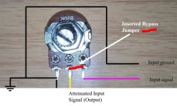
I have illustrated your BYPASS WIRE concept, as I understand it. This looks to make sense to me.
Can I ask you to have a look at my pic and let me know if I have grasped your suggestion correctly?
With this BYPASS WIRE in place - on each pot - will this mean that the pot itself has absolutely no impact on the audio signal?
Yet, does this mean that the pot's impedance value (even at full CW...) still remains in-circuit - which might be helpful with my TISBURY PASSIVE PREAMP?
If not true, I was thinking that I would simply unsolder the INPUT SIGNAL [PINK] and ATTENUATED INPUT SIGNAL (OUTPUT) [YELLOW] wires and connect them - to achieve the same thing, but to ensure that the (bypassed) pot can have no influence over the audio signal.
Thoughts?
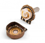
With gain pots fully CW they are pretty much out of the circuit and you still have your original input impedance. You could also solder a short piece of wire across the two ungrounded terminals on the pots and then the contacts inside the pots will be bypassed.
Craig
Thanks for jumping-in here, Craig.
I have illustrated your BYPASS WIRE concept, as I understand it. This looks to make sense to me.
Can I ask you to have a look at my pic and let me know if I have grasped your suggestion correctly?
With this BYPASS WIRE in place - on each pot - will this mean that the pot itself has absolutely no impact on the audio signal?
Yet, does this mean that the pot's impedance value (even at full CW...) still remains in-circuit - which might be helpful with my TISBURY PASSIVE PREAMP?
If not true, I was thinking that I would simply unsolder the INPUT SIGNAL [PINK] and ATTENUATED INPUT SIGNAL (OUTPUT) [YELLOW] wires and connect them - to achieve the same thing, but to ensure that the (bypassed) pot can have no influence over the audio signal.
Thoughts?
Attachments
^ The theory is sound but I would question whether leaving the 100k pot in place is a good idea in practice.
Any slight variability of the pots wiper contact or the mechanical integrity of the pots resistive track to the pin bonding will introduce a random variable load across the passive preamp output.
Also a large pot has the possibility of picking up stray noise and so on.
If you don't want to physically remove the pot then I would look at snipping the leads to it to 100% isolate it and make the new link under the PCB.
It may also be possible to rewire the input RCA direct to the main amp input... only you know that by looking.
I heard that current chooses the path with the least resistance. So I guess your audiosignal will choose to take the link instead of the potmeter. Then no curent will go thru potmeter as if it wasnt there. Maybe one should turn it down to be sure.
About input and output conectors I believe that a good clean and maybe polishing will make them as good as the most expensive conector you can find. As long as you clean then every some years and cut of a bit of the wires. Its not a kilowatt amp. So you dont need thicker wire than they can acomodate.
Congrats on your adventure. You mention magic sometimes and Luxman is the only brand that Ive experienced that can somehow put magic into amplifiers. Ive sometimes wondered if the magic resides somwhere in their preamps or the powersection. I dont own luxman so i have never had the oportunity to mix their pre-outs or main-ins with other stuff. Ive gone another route than luxman, but for a long time I looked for an l430, My friend has it using its turntable input and when we tried two of my speakersets at his place it made them sing as I never could make them at home. L430 has the duobeta circuit I think its called. I wondered if the magic pixies hangs out there- as I heard another luxman with duobeta many years ago that also could transform speakers.
What a great place this forum. Cheers!
Last edited:
You are correct saying the current will take the path of least resistance... which is the link ")
The problem is that the pots fixed 100k resistance (measured end to end) is still across the audio input socket of the amp, and because the preamp is passive that resistance forms a divider in combination with the preamp output impedance (which being a passive preamp is relatively high).
With the link in place, turning the pot 'down' would actually short the incoming audio out.
Turning the pot 'up' to maximum sets it to its highest resistance value (100k) where it has least effect.
Another problem I didn't mention is that pots can have very wide tolerances and that adds a further problem because any difference in resistance will alter the channel balance in an unpredictable way.
Its decided! The MONO Gain Pots need to be Completely Severed!
Thanks for chiming-in GUERILLA. I'm glad you are enjoying this thread.
It was always my hope that this Restoration Project Thread would provide at least as much help and technical support to other AVANCE Z501 Owners, as I've received from the expert members here.
As recommended by PITBUL, I will be replacing the female Input RCAs with something nice. Probably NEUTRIK. They don't cost that much and I have experienced the rewards of installing quality connectors in some of my speaker projects. I too am a believer, in this regard.
MOOLY, many thanks again for your insights. You have convinced me to sever the MONO Gain Pots completely - although I will leave them physically in-place, for aesthetic and originality purposes. That way, there can be no chance that the old 100K Ohm Pots can interfere in any way.
[It it sounds lousy, I'll simply reconnect them... LOL!]
I feel pretty sure that I will figure-out a way to run a fresh - quality - wire from the Inputs directly to the PCB. Actually, I've been saving some high-end, JUPITER Cotton-sleeved OFC Solid Core for a task just like this one. It should be perfect!
As an aside, I had a bit of a listening session today with an Audio-buddy. He runs some VERY nice (modern) SET Monoblocks with large English LIVING VOICE loudspeakers; and has the best ($$$) of everything in his system. He was simply blown-away by the Z501 in our system!
(Proud papa... )
)
So, thanks to you guys and your excellent support, the old girl is very much back on-song.
I'm just curious to see what sort of improvements can be wrought by removing the old MONO Gain Pots from the system. I feel that it will be very worthwhile, because currently there is so much Gain in the Z501, that we only use the lower 20%-25% of the cheap old wiper pots - where we know that the pots are at their sonic worst.
With its abundance of Gain - I'm not sure how much in dB, but it feel like at least 30dB - I feel sure that the Z501 is really begging for a passive preamp.
Let's see...
Thanks for chiming-in GUERILLA. I'm glad you are enjoying this thread.
It was always my hope that this Restoration Project Thread would provide at least as much help and technical support to other AVANCE Z501 Owners, as I've received from the expert members here.
As recommended by PITBUL, I will be replacing the female Input RCAs with something nice. Probably NEUTRIK. They don't cost that much and I have experienced the rewards of installing quality connectors in some of my speaker projects. I too am a believer, in this regard.
MOOLY, many thanks again for your insights. You have convinced me to sever the MONO Gain Pots completely - although I will leave them physically in-place, for aesthetic and originality purposes. That way, there can be no chance that the old 100K Ohm Pots can interfere in any way.
[It it sounds lousy, I'll simply reconnect them... LOL!]
I feel pretty sure that I will figure-out a way to run a fresh - quality - wire from the Inputs directly to the PCB. Actually, I've been saving some high-end, JUPITER Cotton-sleeved OFC Solid Core for a task just like this one. It should be perfect!
As an aside, I had a bit of a listening session today with an Audio-buddy. He runs some VERY nice (modern) SET Monoblocks with large English LIVING VOICE loudspeakers; and has the best ($$$) of everything in his system. He was simply blown-away by the Z501 in our system!
(Proud papa...
) So, thanks to you guys and your excellent support, the old girl is very much back on-song.
I'm just curious to see what sort of improvements can be wrought by removing the old MONO Gain Pots from the system. I feel that it will be very worthwhile, because currently there is so much Gain in the Z501, that we only use the lower 20%-25% of the cheap old wiper pots - where we know that the pots are at their sonic worst.
With its abundance of Gain - I'm not sure how much in dB, but it feel like at least 30dB - I feel sure that the Z501 is really begging for a passive preamp.
Let's see...
Last edited:
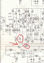
We can get a quick estimate of gain by looking at the feedback network.
The 15k and 470 ohm set the basic gain at (15000/470)+1 which is ~ 33 numerically. So 1 volt in would give 33 volts out. The 15k arrowed which is the servo correction input to the amplifier actually appears in parallel with the 470 ohm because the opamp output is such a low impedance point. So we should really include that in the calculation and say that the 470 ohm really appears as a 456 ohm in the gain calculation.
So the actual gain is nearer 34.
To get that in db we now know 1 volt in would give 34 volts out and so we use the standard 20*log(V1/V2) to get the voltage gain in db which comes out close to 31db gain.
Attachments
That the gain numerically and in db is just a coincidence of the values. If you lincreased the numerical gain to say 150 (so 1 volt in gives 150 volts out) then the db gain would be just 43db.
Similarly if you reduced the numerical gain to just 10 (so 1 volt in gives 10 volts out) then the gain in db would be 20db.
Similarly if you reduced the numerical gain to just 10 (so 1 volt in gives 10 volts out) then the gain in db would be 20db.
Thanks MOOLY.
I'm gonna copy those posts into my own saved "LEARNINGS" folder as I have been unable to find such a cogent explanation of how to calculate Gain and convert to dB - which is the terminology to which I relate.
[I'm not pretending that I understand all of it, but give me time... ]
Nice to see also that my estimate of 30dB was not far off. That's a whole load of Gain huh?
No wonder (clever) Johnny from LUXMAN popped a couple of Gain Pots on this big bad baby...
I'm gonna copy those posts into my own saved "LEARNINGS" folder as I have been unable to find such a cogent explanation of how to calculate Gain and convert to dB - which is the terminology to which I relate.
[I'm not pretending that I understand all of it, but give me time...
]Nice to see also that my estimate of 30dB was not far off. That's a whole load of Gain huh?
No wonder (clever) Johnny from LUXMAN popped a couple of Gain Pots on this big bad baby...
Good innit
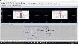
If you look at the whole circuit of your amp you will see it can be considered in many ways to an opamp. It has an inverting input and a non inverting input which are the gates of the two FET's.
Here is a simulation of an opamp (left hand one) with your values plugged in. The input voltage is set to 100mv rms and the output comes out at 3.38 volts. Gain = 33.8 numerically.
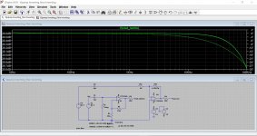
Now we run the simulation to show the output over the whole audio band and we can see the gain (shown as db) is around 30.6 db. Calculator says 30.58db from the above numbers (but they are rounded) so you can see it agrees 100%.
If you look at the whole circuit of your amp you will see it can be considered in many ways to an opamp. It has an inverting input and a non inverting input which are the gates of the two FET's.
Here is a simulation of an opamp (left hand one) with your values plugged in. The input voltage is set to 100mv rms and the output comes out at 3.38 volts. Gain = 33.8 numerically.
Now we run the simulation to show the output over the whole audio band and we can see the gain (shown as db) is around 30.6 db. Calculator says 30.58db from the above numbers (but they are rounded) so you can see it agrees 100%.
Attachments
TISBURY PASSIVE PREAMP Arrives...
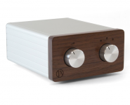
The TISBURY PASIVE PREAMP arrived today, so looking forward to trying it - when time permits.
I have decided to try the TISBURY before bypassing the MONO Gain Pots on the Z501, just to get my ears around how the Z501 sounds at FULL Gain, HALF Gain, etc. etc..
[I am hoping for some sonic improvements with the pots wide open...]
Once completed, I will bypass the pots and report back to round off this thread.
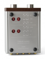
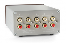
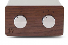
In the meantime, here a few shots of the amazing little TISBURY PASSIVE PREAMP.
With 3-SOURCE INPUTS and 2 MAIN OUTPUTS it's quite the bargain at GBP 149.00.
With RAVE REVIEWS aplenty, this should be very interesting...
The TISBURY PASIVE PREAMP arrived today, so looking forward to trying it - when time permits.
I have decided to try the TISBURY before bypassing the MONO Gain Pots on the Z501, just to get my ears around how the Z501 sounds at FULL Gain, HALF Gain, etc. etc..
[I am hoping for some sonic improvements with the pots wide open...]
Once completed, I will bypass the pots and report back to round off this thread.
In the meantime, here a few shots of the amazing little TISBURY PASSIVE PREAMP.
With 3-SOURCE INPUTS and 2 MAIN OUTPUTS it's quite the bargain at GBP 149.00.
With RAVE REVIEWS aplenty, this should be very interesting...
Attachments
Sondeknz. Do you have the luxkit preamp? Would you maybe find time to pair the two luxkits with eachother and other partners, and describe your feeling about if the special Luxman sound resides in the pre- or the poweramp? That would be very interesting for me and maybe others.
Happy workers day!
Happy workers day!
Hello Sondeknz,
I got your message in the WAM forum and I'm glad to hear the you have finally solved the problem with your Z501 and is working OK now.
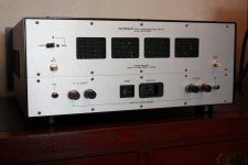
I've not read all the correspondence you have had on this forum but I've seen some. As you know I've got two of them one of which I have had from new in 1982, the other one bought second hand some years ago so I could run them both in bridged mono mode to power each of my speakers.The second one is disassembled at present along with all new parts necessary to rebuild that one (some day).
I also have two Z504 amps and a Z502 pre-amp all of which I have totally rebulit (not just upgraded) as has one of the Z501 amps which I did a few years ago.
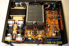
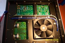
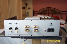
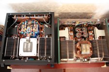
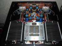
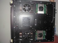
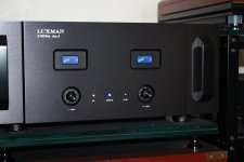
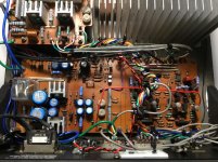
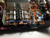
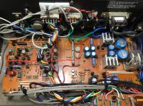
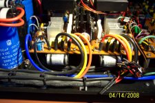
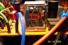
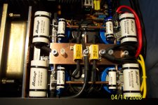
For yourself and anyone that is interested here are some of the upgrades I did to the Z501: First the original chassis was changed for an all aluminium (non magnetic) one. then ALL the electrolytic caps changed for better quality new ones each bypassed with low value quality film caps. The power supply caps were replaced with 'Slit Foil' types and the total capacitance increased from 30,000 to 80,000uf also the 15amp bridge rectifier swapped for 2x 35amp/400v ones due to the increase in capacitance and the possible failure of the supply due to the increased inrush current at startup. All the carbon film resistors changed to 1% metal film types and the original film and mica caps swapped to higher grade ones. All the transistors even the output devices were changed for matched pair ones of similar types.The op-amps were also scrapped and replaced with modern high speed ones (OPA2132PA) supplies bypassed for increased stability. All the wiring swapped for thicker silver plated OFC Teflon insulated cabling.
The input pots changed to some Bourns (Log) types and all the class A/AB bias and DC offset variable resister pots changed to multi-turn quality types. Mains and output fuses now are changed to fast acting circuit breakers. In fact the only original parts of the amp are the circuit boards (in good condition) the heat ex-changer and the mains transformer!.
More detailed explanations of the upgrades can be provided to yourself or anyone else that's interested if required.
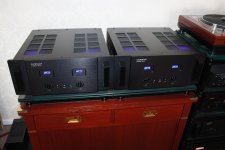
The rebuild was a worthwhile project and transformed the amp from a good mid powered power amp to a great one (in my opinion). There are one or two attachments below which will give you (some) idea of what I just spoke about. As I said - I also have two Z504 power amps which I have totally rebuilt and they are 'something else' they will power any speaker on the market with between 600 and 700watts per channel in bridged mono (one for each speaker). Details of these amps rebuilds can also be given to any other 'audiophile' (I hate that weird sounding word) who wants to know. One or two attachments of both amps below for reference - plenty more detailed ones also.
Regards Sondeknz over there in New Zealand, Alv.
I got your message in the WAM forum and I'm glad to hear the you have finally solved the problem with your Z501 and is working OK now.
I've not read all the correspondence you have had on this forum but I've seen some. As you know I've got two of them one of which I have had from new in 1982, the other one bought second hand some years ago so I could run them both in bridged mono mode to power each of my speakers.The second one is disassembled at present along with all new parts necessary to rebuild that one (some day).
I also have two Z504 amps and a Z502 pre-amp all of which I have totally rebulit (not just upgraded) as has one of the Z501 amps which I did a few years ago.
For yourself and anyone that is interested here are some of the upgrades I did to the Z501: First the original chassis was changed for an all aluminium (non magnetic) one. then ALL the electrolytic caps changed for better quality new ones each bypassed with low value quality film caps. The power supply caps were replaced with 'Slit Foil' types and the total capacitance increased from 30,000 to 80,000uf also the 15amp bridge rectifier swapped for 2x 35amp/400v ones due to the increase in capacitance and the possible failure of the supply due to the increased inrush current at startup. All the carbon film resistors changed to 1% metal film types and the original film and mica caps swapped to higher grade ones. All the transistors even the output devices were changed for matched pair ones of similar types.The op-amps were also scrapped and replaced with modern high speed ones (OPA2132PA) supplies bypassed for increased stability. All the wiring swapped for thicker silver plated OFC Teflon insulated cabling.
The input pots changed to some Bourns (Log) types and all the class A/AB bias and DC offset variable resister pots changed to multi-turn quality types. Mains and output fuses now are changed to fast acting circuit breakers. In fact the only original parts of the amp are the circuit boards (in good condition) the heat ex-changer and the mains transformer!.
More detailed explanations of the upgrades can be provided to yourself or anyone else that's interested if required.
The rebuild was a worthwhile project and transformed the amp from a good mid powered power amp to a great one (in my opinion). There are one or two attachments below which will give you (some) idea of what I just spoke about. As I said - I also have two Z504 power amps which I have totally rebuilt and they are 'something else' they will power any speaker on the market with between 600 and 700watts per channel in bridged mono (one for each speaker). Details of these amps rebuilds can also be given to any other 'audiophile' (I hate that weird sounding word) who wants to know. One or two attachments of both amps below for reference - plenty more detailed ones also.
Regards Sondeknz over there in New Zealand, Alv.
Attachments
-
 Amp photos_0012.JPG844 KB · Views: 329
 -
 Amp photos_0070.JPG738.9 KB · Views: 176
 -
 HPIM0468.jpg651.4 KB · Views: 125
 -
 Amp photos_0014.JPG435.4 KB · Views: 125
 -
 IMG_5312.JPG820.9 KB · Views: 136
 -
 HPIM0153.jpg887.4 KB · Views: 324
 -
 HPIM0531.jpg804.2 KB · Views: 122
 -
 IMG_6154.jpg733.6 KB · Views: 108
 -
 IMG_6155.jpg725.2 KB · Views: 132
 -
 IMG_5333.jpg825.2 KB · Views: 125
Hey GUERILLA
I'm sorry that I don't have the LUXKIT (matching) preamp - never seen of heard on - so I can't comment on it at all.
I do believe there is a fair amount of the audiophile "magic" you mention, inherrent in the Z501 Power Amp design.
Sorry I can't offer more.
I'm sorry that I don't have the LUXKIT (matching) preamp - never seen of heard on - so I can't comment on it at all.
I do believe there is a fair amount of the audiophile "magic" you mention, inherrent in the Z501 Power Amp design.
Sorry I can't offer more.
Last edited:
For yourself and anyone that is interested here are some of the upgrades I did to the Z501: First the original chassis was changed for an all aluminium (non magnetic) one. then ALL the electrolytic caps changed for better quality new ones each bypassed with low value quality film caps. The power supply caps were replaced with 'Slit Foil' types and the total capacitance increased from 30,000 to 80,000uf also the 15amp bridge rectifier swapped for 2x 35amp/400v ones due to the increase in capacitance and the possible failure of the supply due to the increased inrush current at startup. All the carbon film resistors changed to 1% metal film types and the original film and mica caps swapped to higher grade ones. All the transistors even the output devices were changed for matched pair ones of similar types.The op-amps were also scrapped and replaced with modern high speed ones (OPA2132PA) supplies bypassed for increased stability. All the wiring swapped for thicker silver plated OFC Teflon insulated cabling.
The input pots changed to some Bourns (Log) types and all the class A/AB bias and DC offset variable resister pots changed to multi-turn quality types. Mains and output fuses now are changed to fast acting circuit breakers. In fact the only original parts of the amp are the circuit boards (in good condition) the heat ex-changer and the mains transformer!.
Hey ALV
Many thanks for chiming-in here.
That is a truly impressive effort... BRAVO!!!
I barely recognised your photos of the Z501 LOL!
Glad to read that you didn't lose any of the original LUXMAN design "Magic".
That's some very nice looking gear you got, right there!
Last edited:
WRAP-UP! Last Glimpses...
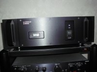
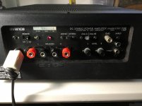
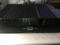
Here are some last shots of our 1981 LUXMAN LUXKIT AVANCE Z501, as we wrap her up in her original enclosure.
Last, but not least, I elected to fit her out with modern Speaker Binding Posts. These ones are as tough as they get and they bolt into the original metal mounting plate. I felt they looked quite original too.
Attachments
Last edited:
Hello again SONDEKNZ,
Got your comments on the WAM forum again, and as far as the change in sound quality is concerned after all the upgrades (don't forget I changed most of the components: capacitors/cabling/pots/op-amps/switches/fuses etc). Possibly mostly due to the increased in uf and quality of the resv. capacitors and better/faster op-amps plus other mods, the amps seems to sound faster more dynamic with a better grip on the bass etc. and if anything an increase in low level detail, this probably due to the fact that I stuck to a 'star earthing' arrangement - there isn't any audible hum/hiss from the speakers with the volume turned way up.
Concerning the Bias (idling current) adjustments question this is normally done prior to the DC offset check and best done using a DMM not an analogue meter. The information given in the workshop manual (do you have one?) is a bit misleading and wrong in my opinion. Before any adjustments are done you should disconnect the speakers and with nothing connected to the inputs turn the pots to the minimum. I did class AB Bias first and the way I did it was to unsolder and lift the wire link to J1 from B9 (L-CH) and to J2 from B11 (R-CH) on CB-501P c/board - I do both channels at the same time using two DMMs, if you only own 1 meter just do one at a time obviously but saves time using two.
Put the meter in the 200mA DC range and clip the Red test lead to B9 and the Black test lead to J1 (L-CH) switch on the amp and leave to settle for about 15 mins. or so before adjusting anything as you will probably find that the current is high initially but will settle lower soon. (If needed) adjust the Bias current up or down as required to obtain 160mA on the meter by turning v/resistor AB-1 (L-CH) clockwise or anticlockwise to suit - careful these are fairly course pots and the value changes quickly, I got rid of these in preference to multi-turn types. Repeat as above for the R-CH by lifting the link wire from J2 and clip the test leads on B11 (red) and J2 (black). After switching back on prob best to leave to stabilize again and then adjust (if necessary) to 160mA as before via AB-1 (R-CH) Done.
For class A Bias adjustments leave everything connected as it is and power down the amp before switching to class A mode. Before switching the amp on again change the meter setting to the 2amp DC (or greater) position. After switching back on leave to settle again for a while before any adjustments done, if needed alter the current via v/resistor A-1 on whichever channel you are doing to 1.25A DC again leave the amp running for a few more mins. and recheck current, when happy power down again and do the other channel the same way, once done power down/disconnect/re-solder the wire links, Done.
As I said it's much less hassle if you can do both channels at the same time!
Prob best to recheck the DC Offsets now again - you don't need to connect the test leads to P1 to GND and P2 to GND for this, you can just put the leads across the speaker binding posts if you prefer. Hope the above helps and let me know if yo have any question on it though I don't think you should have any problems if you follow the method here.
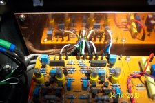
As far as some detailed wiring pics go, I don't have too much but I did do a few internal photo's for my own reference at the time but not sure if they would be of any practical use to yourself? Below are a few anyway. Also I do have a good review on the Z501 (and the Z502 preamp) from a hifi mag here in the UK in 1982 but best not to upload to the forum due any possible copyright issues!
While I remember - I know that film caps aren't supposed to deteriorate much over time normally but the long thin grey film caps 0.47uf/250v on the power supply PCB also on the CB-A501P board and the 2.2uf ones across the resv. caps are suspect as some of the original ones on my Z501were way out of spec. some a bit high but two or three VERY low in value and one was open circuit (amp working OK though). Might be a good idea to check the values (lift one leg of cap first), but of course you will need a capacitance meter for this. A cap meter is a useful tool to have but an even better one is a cap ESR meter but these tend to be a bit more expensive.
Hope ALL the above is of use to you and you get around to making use of some of it. Regards, Alv.
Got your comments on the WAM forum again, and as far as the change in sound quality is concerned after all the upgrades (don't forget I changed most of the components: capacitors/cabling/pots/op-amps/switches/fuses etc). Possibly mostly due to the increased in uf and quality of the resv. capacitors and better/faster op-amps plus other mods, the amps seems to sound faster more dynamic with a better grip on the bass etc. and if anything an increase in low level detail, this probably due to the fact that I stuck to a 'star earthing' arrangement - there isn't any audible hum/hiss from the speakers with the volume turned way up.
Concerning the Bias (idling current) adjustments question this is normally done prior to the DC offset check and best done using a DMM not an analogue meter. The information given in the workshop manual (do you have one?) is a bit misleading and wrong in my opinion. Before any adjustments are done you should disconnect the speakers and with nothing connected to the inputs turn the pots to the minimum. I did class AB Bias first and the way I did it was to unsolder and lift the wire link to J1 from B9 (L-CH) and to J2 from B11 (R-CH) on CB-501P c/board - I do both channels at the same time using two DMMs, if you only own 1 meter just do one at a time obviously but saves time using two.
Put the meter in the 200mA DC range and clip the Red test lead to B9 and the Black test lead to J1 (L-CH) switch on the amp and leave to settle for about 15 mins. or so before adjusting anything as you will probably find that the current is high initially but will settle lower soon. (If needed) adjust the Bias current up or down as required to obtain 160mA on the meter by turning v/resistor AB-1 (L-CH) clockwise or anticlockwise to suit - careful these are fairly course pots and the value changes quickly, I got rid of these in preference to multi-turn types. Repeat as above for the R-CH by lifting the link wire from J2 and clip the test leads on B11 (red) and J2 (black). After switching back on prob best to leave to stabilize again and then adjust (if necessary) to 160mA as before via AB-1 (R-CH) Done.
For class A Bias adjustments leave everything connected as it is and power down the amp before switching to class A mode. Before switching the amp on again change the meter setting to the 2amp DC (or greater) position. After switching back on leave to settle again for a while before any adjustments done, if needed alter the current via v/resistor A-1 on whichever channel you are doing to 1.25A DC again leave the amp running for a few more mins. and recheck current, when happy power down again and do the other channel the same way, once done power down/disconnect/re-solder the wire links, Done.
As I said it's much less hassle if you can do both channels at the same time!
Prob best to recheck the DC Offsets now again - you don't need to connect the test leads to P1 to GND and P2 to GND for this, you can just put the leads across the speaker binding posts if you prefer. Hope the above helps and let me know if yo have any question on it though I don't think you should have any problems if you follow the method here.
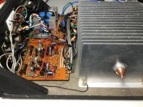
As far as some detailed wiring pics go, I don't have too much but I did do a few internal photo's for my own reference at the time but not sure if they would be of any practical use to yourself? Below are a few anyway. Also I do have a good review on the Z501 (and the Z502 preamp) from a hifi mag here in the UK in 1982 but best not to upload to the forum due any possible copyright issues!
While I remember - I know that film caps aren't supposed to deteriorate much over time normally but the long thin grey film caps 0.47uf/250v on the power supply PCB also on the CB-A501P board and the 2.2uf ones across the resv. caps are suspect as some of the original ones on my Z501were way out of spec. some a bit high but two or three VERY low in value and one was open circuit (amp working OK though). Might be a good idea to check the values (lift one leg of cap first), but of course you will need a capacitance meter for this. A cap meter is a useful tool to have but an even better one is a cap ESR meter but these tend to be a bit more expensive.
Hope ALL the above is of use to you and you get around to making use of some of it. Regards, Alv.
Attachments
-
 Amp photos_0084.JPG691.9 KB · Views: 91
 -
 Amp photos_0026.JPG524.6 KB · Views: 98
 -
 Amp photos_0024.JPG632.2 KB · Views: 108
 -
 Amp photos_0027.JPG515.6 KB · Views: 80
 -
 Amp photos_0080.JPG702.4 KB · Views: 110
 -
 Amp photos_0089.JPG594.9 KB · Views: 83
 -
 Amp photos_0047.JPG631.8 KB · Views: 80
 -
 Amp photos_0063.JPG758.8 KB · Views: 76
 -
 Amp photos_0078.JPG610.9 KB · Views: 76
 -
 Amp photos_0029.JPG632.8 KB · Views: 149
- Status
- This old topic is closed. If you want to reopen this topic, contact a moderator using the "Report Post" button.
- Home
- Amplifiers
- Solid State
- A501 / Z501 Luxkit Amplifier schematic