Yup it's been done, back in the Audio Amatuer, ummm not sure what year, randolph Vikan submitted a letter detailing his construction using the Hitachi lateral's 2SJ49\2SK134.
you could use the Exicon's or Renasis MOSFETs now.
Also the letter contains a response from Nelson.
you would of coarse need to alter the values in the bias divider.
you could use the Exicon's or Renasis MOSFETs now.
Also the letter contains a response from Nelson.
you would of coarse need to alter the values in the bias divider.
Another option is to create your own darlingtons by mounting the other transistor next to the output transistors of your choice and the resistor as well . A little extra fuss ( o.k. a lot) but you end up with a pretty high performance darlington. IMO having a driver for each ouput is an important contributer in the exceptional ability of this amp to drive impossible loads. I have driven speakers of less than 1ohm with no ill efects or rudeness.
BTW I share your opinion of the TIP devices they are slow, and the internal resistor does not provide for enough current to deliver the kind of performance we are after here.
BTW I share your opinion of the TIP devices they are slow, and the internal resistor does not provide for enough current to deliver the kind of performance we are after here.
well yeah ....
if you need to actually construct 8 darligtons and wire them properly and so on and on in a pcb that works with leads from to transistors ....then you might as well redesign the pcb while keeping all design rules and then you will end up with a serious amp ....
will see not ready for a think like that ( too busy ) on the other hand i might as well go hunting for the best tip 142-147 i can find in the market and construct as is ...listen ....and may be redesign the all thing if sounds well ...
i am quiet not easy person to be impressed by a class a design .... i am actually a SA1302 -3281 person working in AB .....
do i need a therapist ????? ha ha ha ha
since sakis is quiet busy
with rentals and other projects ...i will complete the first stages of this project for him ...
so i have a couple of questions .....
1- the input filter capacitor is a 300pf silver mica the closest available we have is 390.... good quality silver mika will this make serious changes to the performance of the amp ????
2-then tantalium caps are placed in a couple of points there will it make any chnge to use simple electro's for that ???
3- finally will it be nice to bypass them with nice styroflex 100nf ???
thank you very much
sierra mike ( working for sakis )
I built two A40's back when the amp design was first published.
IMHO the answers to your questions are:
1) I don't think you'll hear any difference going to 390pf. This capacitor is present primarily to remove RF from the input.
2) Do not use tantalum caps! They sound terrible. I discovered this on my own back in the 1970's. Many people have made similar findings and reported them. The current popular cap choice is the Elna silk line.
3) I don't know. But it's cheap and easy to experiment and make the decision yourself.
Good luck with your project. This amp is one of the true classics of DIY.
Graeme

Correct ....
THIS IS WHAT I THOUGHT ALSO ........
especially looking at the original pdf on pass labs ....
did we miss something on the way papa????
TIP142-147 BDV66-67 and related cousins ....
the bad reputation about these devices lays arround one thing only ..... durability and stability .....
But where this comes from ????
most people that had circuits working with these devices missed one thing :
Draligtons have diferent makes depenting on the make , the application , the original order , costumer specs and so on and on and on ....
meaning that if you have 2x2N3055 in one amplifier and the first is ONSEMI and the other is MOTOROLA you have a chance .... but if you have a TIP 142 from philips and TIP 147 from SGS it simply doesnt work ....
the bigest reason is that you dont know which is the exact configuration between the driver and the output tranistor .... one ismade with A resistor other ismade with B resistor and so onand on and on ....
if its a lofi application all is fine but if the circuit/application creates stress to the outputs then death and smoke is just a matter of time .....
Never the less let us not forget that darligtons often can be taken as mosftes IE if the design is not proper for them oscilation is waiting arround the corner....
Take as a fact that almost non of comercial equipment ever used this familly except some philips amps and some BO sets that if broken the repair is a nightmare .....
Funny part .....
somewhere in the net exists the john fisher amplifier that clames 100-150w power with the lowest part count you can ever imagine he he he he I think that this amp must be constructed by so many (built with 142-147 ) and now days i think that all these people support and keep demands for production of 142-147.. family .....
the "thing" has a very catchy title he he he
any news any one ????
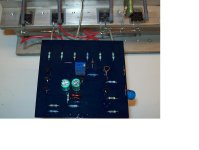
sierra mike constructed a prototype for me
used mpsa 42-92, electro's in place of the tantalium , tip 142+147 for outs and a resistor for curent source insted of the unobtainable 2N5248
from a safety point of view and easier tuning R11 is replace with 10k multiturn
C4 was a multilayer 20pf
havent done much of testing on the amp, bias network is working and you can obtain easy a bias of 1mv-100mv over 0.68 resistors but if bias is higher than 5 mv then oscilation starts ...
will have to check again ...it doesnt look good
will do will do
while constructing i always make a demo of the amp to take a first look ....
then actually my "mechano" skills are almost 10 times better than my theoretical approach ....meaning that if i have a well working circuit then the peripherals are going to be superb ....
give it a few days ...will post my results soon ....photos also
by the way
any drop in replacement for 2N5248 ?????
A look in the snailmail can and ...out comes envelope from Forest Hills CA, rip open and behold, it is a ....stereo errrrr something else.
Hmmm reverse engineering my favorite kind. No silkscreening so this will be a little more of a challenge.
well each channel has an input and an output 1 and an output 2
well could be a bridging adapter, but that jut doesn't sound like a Pass sort of thing to do, that just adds unnecessary circuitry.
so... could be a biamping crossover or. My first real guess is .........
The B2 Biamp Buffer. You say you tried bi-amping but didn’t get sound you wanted? The B2 uses two pairs of the buffers found in the B1 but configured for splitting the output of the preamp with variable relative gain to two sets of power amplifiers. This allows not only isolated amplifier impedance buffering, but adjusts the gain levels for different amplifiers. Even for identical amplifier channels it also allows the subtle adjustment required to get exactly the top/bottom balance you need.
So If my hunch is right I should see 4 T092 pack outlines and probably a pair of trimpots on each half .....hmmm time to fire up the scanner and start doodling.
This is my kind of puzzle, Figuring out what an engineer was thinking ( Or is it what the hell was that engineer thinking). Not so this time I know where it came from.
.
Ah but the Aleph front panel now must go back on the Bridgeport to mil out an appropriate window for those spiffy PASSDIY labels.
Thanks Nelson you are way too kind .

MINE .....
is ready and working allright but it will have to freeze for a while before get ready to be a ready made device since no decent tip142-147 are found in the Greek market yet and then on the other hand i dont really wana go for cans ..... too much mechano to do that i am not up to these days
also another reason to freeze this is that the mosfet used for a current source is almost impossible to get ( as we speak only one resistor+cap is used ) so this part needs to be redesigned ....
the pcb is the original but i am actually tempted to make my own since i really dont like outputs wired to the pcb ..... this is something i would never do .....
regards sakis
PS .... it measures pretty fine but still havent heard anything from it ....i dont wana spoil my ears before everything very ready first ..... ha ha ha
Attachments
Re: will do will do
The only one I notice about by Eric in his website is the nte312.
However, I saw also people speaking about j204.
As Nelson wrote in his part substitution article, this device is required to garantee a 3mA current in association with R9.
So, as a beginner, could I think to use the however Jfet (instead 2n5248) in association with the right R9 in order to get the approx. 3mA at r9?
Sorry if I said something stupid.
sakis said:
by the way
any drop in replacement for 2N5248 ?????
The only one I notice about by Eric in his website is the nte312.
However, I saw also people speaking about j204.
As Nelson wrote in his part substitution article, this device is required to garantee a 3mA current in association with R9.
So, as a beginner, could I think to use the however Jfet (instead 2n5248) in association with the right R9 in order to get the approx. 3mA at r9?
Sorry if I said something stupid.
- Status
- This old topic is closed. If you want to reopen this topic, contact a moderator using the "Report Post" button.
- Home
- Amplifiers
- Pass Labs
- A40 PCBs