"The Ultimate Suplifier"
from Marc
http://www.esafono.it/Suplifier.zip
it's important select gain (hFE) on final devices
easy create copules with 2SA1302 and 2SC5200
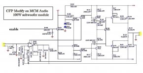
see also another example from
http://www.mcmelectronics.com/content/ProductData/Spec Sheets/50-6263.pdf
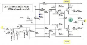
then my modify to CFP
from Marc
http://www.esafono.it/Suplifier.zip
it's important select gain (hFE) on final devices
easy create copules with 2SA1302 and 2SC5200
see also another example from
http://www.mcmelectronics.com/content/ProductData/Spec Sheets/50-6263.pdf
then my modify to CFP
Attachments
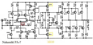
complete scheme of PA-7
http://www.esafono.it/pa-7.pdf
that is intresting because suggest to use 7 pair of 2A device @47V
http://www.esafono.it/pa-7.pdf
that is intresting because suggest to use 7 pair of 2A device @47V
Re: complete scheme of PA-7
I read 2A @ 65Vce & Tc=25degC.
the 7pair 2sa1294/2363 devices are Sanken 130W 15A 230V not 2A @47Vce.Stee said:
I read 2A @ 65Vce & Tc=25degC.
Re: Re: complete scheme of PA-7
hello andrew !!! happy new year !!!
can i have your opinion about this ?????
if its possible to operate this in norma class AB ???
AndrewT said:the 7pair 2sa1294/2363 devices are Sanken 130W 15A 230V not 2A @47Vce.
I read 2A @ 65Vce & Tc=25degC.
hello andrew !!! happy new year !!!
can i have your opinion about this ?????
if its possible to operate this in norma class AB ???
Re: see Nakamiki version
The output stage has a bigger gain than cfp ... and is not linnear.The Vas current source don't have bigger dynamics because it have the voltage reference 2 diodes;the beta helper with another bipolar has more dinamics .
This amp is colouring the sound in a good way but don't reproduce the original sound .This is my oppinion . In next year when I will have time I will try to colour the sound by introducing h2 ... Excuse my english
A beautiful year and a coloured one ..
Happy new year !
The nakamichi is a good design.Is good for those who like to colour the sound... The output stage is not included in the negative loop .The nonlinerities of the output stage will be present on output.Stee said:I think is Stasis VAS
The output stage has a bigger gain than cfp ... and is not linnear.The Vas current source don't have bigger dynamics because it have the voltage reference 2 diodes;the beta helper with another bipolar has more dinamics .
This amp is colouring the sound in a good way but don't reproduce the original sound .This is my oppinion . In next year when I will have time I will try to colour the sound by introducing h2 ... Excuse my english
A beautiful year and a coloured one ..
Happy new year !
Thank you Stefano fot publishing "The Ultimate Suplifier" in your website (see post 83).
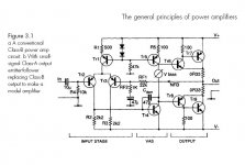
Who will take the challenge to use my output configuration (see figure 1 in the explanation of the Ultimate Suplifier) in the V3 circuit (see post 75)?? The only thing you have to change for a higher supply voltage, is to raise R39/R40 to 56 ohm. Because 2 transistors are added (Q13 and Q14) the Vbias must be higher which can be achieved by lowering R29 in the V3 circuit to 0 ohm. Of course the output "from the neg. amplifier" must be connected to the ground.
A sziklai pair sometimes tends to oscillate. Therefor the output resistors may not be wired but must be of carbon. 5 resistors of 1,2 ohm and 1 resistor of 2,7 ohm parallel gives 0,22 ohm.
If, by the reason of the overall neg. feedback, there is still some oscillation, try capacitors parallel to R39 and R40 with a - 3 dB point above lets say 200 kHz. This will be (for R39/49 = 56 ohm) 15 nF each.
Andrew, which schematic dou you refer to? If you mean the attached file, then I agree this is a potentionally thermal instabel output. The emittor of Q111 should be connected to the emittor of Q114 and the emittor of Q112 to the emittor of Q113. Then you have to match Q114 with Q116 and Q113 with Q115 otherwise there is a change of thermal runaway of Q116 and Q115.
Marc.
Attachments
sorry
I have generate some confusing...
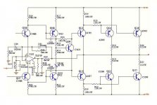
try again to convert in CFP output a "normal " amp:
http://www.mcmelectronics.com/content/ProductData/Spec Sheets/50-6272.pdf

need just two resistors 120R
I have generate some confusing...
try again to convert in CFP output a "normal " amp:
http://www.mcmelectronics.com/content/ProductData/Spec Sheets/50-6272.pdf
need just two resistors 120R
Attachments


New Frontiers
http://www.ampslab.com/bi70mk2.htm
as FET on input
now
is time to lighten the load on VAS
with Mos Drivers
http://www.ampslab.com/bi70mk2.htm
as FET on input
now
is time to lighten the load on VAS
with Mos Drivers
Attachments
- Status
- This old topic is closed. If you want to reopen this topic, contact a moderator using the "Report Post" button.
- Home
- Amplifiers
- Solid State
- a wonderfull sziklai